SiplaceX4_en.pdf - 第71页
S tudent Guide SIPLACE X Edition 09/2005 Inhalt 1 Chapter T able of content s 3 Communication and Control . . . . . . . . . . . . . . . . . . . . . . . . . . . . . . . . . . . . . . . . . . 3 3.1 Communication Overview .…
1 - 46
Student Guide SIPLACE X
2 Overview Edition 09/2005
46
2.2.13.2 Construction of Single Conveyor
The single conveyor consists of the input conveyor, two placements areas, intermediate conveyor
and output conveyor. Each conveyor has automatic width adjustment and a lifting table for clamp-
ing the PCB.
Fig. 2.2 - 29 Construction of PCB conveyor
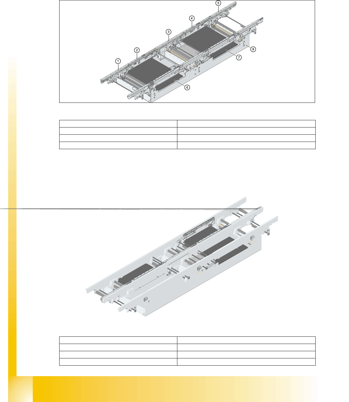
2.2.13.3 Construction of Dual Conveyor
Dual conveyors have two transportation tracks (1 and 2). In the standard conveyor, the right-hand
side of each track is the fixed side. The fixed conveyor side can be changed to the left, where re-
quired.
Fig. 2.2 - 30 Construction of dual conveyort
(1)Input conveyor (2)Conveyor for placement area 1
(3)Intermediate conveyor (4)Conveyor for placement area 2
(5)Output conveyor (6)Lifting table 1
(7)Lifting table 2 (8)Conveyor vat
(1)Input conveyor (2)Conveyor for placement area 1
(3)Lifting table 1 (4)Intermediate conveyor
(5)Conveyor for placement area 2 (6)Lifting table 2
(7)Output conveyor (8)Conveyor vat

Student Guide SIPLACE X
Edition 09/2005 Inhalt
1
Chapter
Table of contents
3 Communication and Control . . . . . . . . . . . . . . . . . . . . . . . . . . . . . . . . . . . . . . . . . . 3
3.1 Communication Overview. . . . . . . . . . . . . . . . . . . . . . . . . . . . . . . . . . . . . . . . . . . . . . . . . . . . . . . . . 3
3.1.1 Networking Overview. . . . . . . . . . . . . . . . . . . . . . . . . . . . . . . . . . . . . . . . . . . . . . . . . . 4
3.2 Networking Address . . . . . . . . . . . . . . . . . . . . . . . . . . . . . . . . . . . . . . . . . . . . . . . . . . . . . . . . . . . . . 5
3.2.1 Check the network addresses . . . . . . . . . . . . . . . . . . . . . . . . . . . . . . . . . . . . . . . . . . . 5
3.2.1.1 Stationscomputer . . . . . . . . . . . . . . . . . . . . . . . . . . . . . . . . . . . . . . . . . . . . . . . . . 5
3.2.1.2 Machinecontroller (MC) . . . . . . . . . . . . . . . . . . . . . . . . . . . . . . . . . . . . . . . . . . . . 6
3.2.2 Computer at the LAN Network . . . . . . . . . . . . . . . . . . . . . . . . . . . . . . . . . . . . . . . . . . 7
3.2.3 Communication on placement machine . . . . . . . . . . . . . . . . . . . . . . . . . . . . . . . . . . . 9
3.2.4 Machine Controller Communication . . . . . . . . . . . . . . . . . . . . . . . . . . . . . . . . . . . . . . 9
3.3 CAN Bus . . . . . . . . . . . . . . . . . . . . . . . . . . . . . . . . . . . . . . . . . . . . . . . . . . . . . . . . . . . . . . . . . . . . . . 11
3.3.1 History of CAN. . . . . . . . . . . . . . . . . . . . . . . . . . . . . . . . . . . . . . . . . . . . . . . . . . . . . . 11
3.3.2 CAN Bus in General . . . . . . . . . . . . . . . . . . . . . . . . . . . . . . . . . . . . . . . . . . . . . . . . . 13
3.3.2.1 11 Bit Identifier . . . . . . . . . . . . . . . . . . . . . . . . . . . . . . . . . . . . . . . . . . . . . . . . . . 14
3.3.2.2 CAN Bus protocol. . . . . . . . . . . . . . . . . . . . . . . . . . . . . . . . . . . . . . . . . . . . . . . . 14
3.3.2.3 CSMA: Collusion Detectection . . . . . . . . . . . . . . . . . . . . . . . . . . . . . . . . . . . . . . 15
3.3.2.4 CAN Bus Arbitration . . . . . . . . . . . . . . . . . . . . . . . . . . . . . . . . . . . . . . . . . . . . . . 15
3.3.3 CAN Bus Concept SiplaceX4 . . . . . . . . . . . . . . . . . . . . . . . . . . . . . . . . . . . . . . . . . . 17
3.3.4 CAN Bus Concept SiplaceX3 . . . . . . . . . . . . . . . . . . . . . . . . . . . . . . . . . . . . . . . . . . 18
3.3.5 CAN Bus Concept SiplaceX2 . . . . . . . . . . . . . . . . . . . . . . . . . . . . . . . . . . . . . . . . . . 19
3.3.6 CAN-Bus Concept with One Wire Bus e.g. SiplaceX3 . . . . . . . . . . . . . . . . . . . . . . . 20
3.3.7 CAN Bus Processor Board C&P Head . . . . . . . . . . . . . . . . . . . . . . . . . . . . . . . . . . . 21
3.3.7.1 CAN Bus controlled function on 6/12C&P Head. . . . . . . . . . . . . . . . . . . . . . . . . 21
3.3.7.2 CAN-Bus controlled function on C&P 20 Kopf . . . . . . . . . . . . . . . . . . . . . . . . . . 22
3.3.8 CAN Bus controlled function on the Twin Head . . . . . . . . . . . . . . . . . . . . . . . . . . . . 23
3.3.9 CAN I/O Module (SLIO) Siplace X. . . . . . . . . . . . . . . . . . . . . . . . . . . . . . . . . . . . . . . 24
3.3.9.1 DIP Switch on the Main- and Sub Distributor . . . . . . . . . . . . . . . . . . . . . . . . . . . 25
3.3.10 CAN: Bus Communication with Axis Controller. . . . . . . . . . . . . . . . . . . . . . . . . . . . 30
3.3.11 Communication Siplace Vision . . . . . . . . . . . . . . . . . . . . . . . . . . . . . . . . . . . . . . . . 31
3.3.11.1 Communication during a image acquisition . . . . . . . . . . . . . . . . . . . . . . . . . . . 32
3.3.12 Communikation C&P 20 Head. . . . . . . . . . . . . . . . . . . . . . . . . . . . . . . . . . . . . . . . . 33
3.3.13 Communication X-Feeder . . . . . . . . . . . . . . . . . . . . . . . . . . . . . . . . . . . . . . . . . . . . 34
3.4 Axis control . . . . . . . . . . . . . . . . . . . . . . . . . . . . . . . . . . . . . . . . . . . . . . . . . . . . . . . . . . . . . . . . . . . 35
3.4.1 Position measuring system . . . . . . . . . . . . . . . . . . . . . . . . . . . . . . . . . . . . . . . . . . . . 35
3.4.1.1 Track signals and Zero pulse signal . . . . . . . . . . . . . . . . . . . . . . . . . . . . . . . . . . 35

1 - 2
Student Guide SIPLACE X
Inhalt Edition 09/2005
2
3.4.1.2 Zero pulse at the position encoder . . . . . . . . . . . . . . . . . . . . . . . . . . . . . . . . . . . 37
3.4.2 Axis dynamic basics . . . . . . . . . . . . . . . . . . . . . . . . . . . . . . . . . . . . . . . . . . . . . . . . . 38
3.4.3 Axis controller . . . . . . . . . . . . . . . . . . . . . . . . . . . . . . . . . . . . . . . . . . . . . . . . . . . . . . 42
3.4.3.1 Servo amplifier TBS .. and SDS ... . . . . . . . . . . . . . . . . . . . . . . . . . . . . . . . . . . 43
3.5 One Wire Bus . . . . . . . . . . . . . . . . . . . . . . . . . . . . . . . . . . . . . . . . . . . . . . . . . . . . . . . . . . . . . . . . . . 45
3.5.1 One Wire Bus - Structure. . . . . . . . . . . . . . . . . . . . . . . . . . . . . . . . . . . . . . . . . . . . . . 45
3.5.1.1 Basic Structure . . . . . . . . . . . . . . . . . . . . . . . . . . . . . . . . . . . . . . . . . . . . . . . . . . 45
3.5.1.2 One Wire Bus in the HF Machines . . . . . . . . . . . . . . . . . . . . . . . . . . . . . . . . . . . 46
3.5.1.3 One Wire Bus in the Siplace X . . . . . . . . . . . . . . . . . . . . . . . . . . . . . . . . . . . . . . 47
3.5.2 Function Control and Troubleshooting for Service Work. . . . . . . . . . . . . . . . . . . . . . 52
3.5.2.1 Subsystem Query in PA1 . . . . . . . . . . . . . . . . . . . . . . . . . . . . . . . . . . . . . . . . . . 52
3.5.2.2 Function Control with Caccia . . . . . . . . . . . . . . . . . . . . . . . . . . . . . . . . . . . . . . . 55
3.5.3 One wire Bus Siplace X machine . . . . . . . . . . . . . . . . . . . . . . . . . . . . . . . . . . . . . . . 59
3.5.3.1 Communication One Wire. . . . . . . . . . . . . . . . . . . . . . . . . . . . . . . . . . . . . . . . . . 59
3.5.3.2 Overview Initialization of the One Wire Bus . . . . . . . . . . . . . . . . . . . . . . . . . . . . 60
3.6 Board type recognition . . . . . . . . . . . . . . . . . . . . . . . . . . . . . . . . . . . . . . . . . . . . . . . . . . . . . . . . . . 63
3.6.1 What does it mean board type recognition? . . . . . . . . . . . . . . . . . . . . . . . . . . . . . . . 63
3.6.1.1 Why we integrate the board type recognition? . . . . . . . . . . . . . . . . . . . . . . . . . . 63
3.6.1.2 Functional description. . . . . . . . . . . . . . . . . . . . . . . . . . . . . . . . . . . . . . . . . . . . . 63
3.6.1.3 Error description: . . . . . . . . . . . . . . . . . . . . . . . . . . . . . . . . . . . . . . . . . . . . . . . . 63
3.6.1.4 PCB‘s with board type ID‘s . . . . . . . . . . . . . . . . . . . . . . . . . . . . . . . . . . . . . . . . . 65
3.6.2 Check and write of the board type ID‘s on the EEPROM . . . . . . . . . . . . . . . . . . . . . 65
3.6.2.1 Read out the Board type ID via the menu Gripper . . . . . . . . . . . . . . . . . . . . . . . 66
3.6.2.2 Read and write the Board type ID with CAN commands . . . . . . . . . . . . . . . . . . 69
3.6.3 Troubleshooting, if are missing two board type ID‘s . . . . . . . . . . . . . . . . . . . . . . . . . 73
3.6.4 CAN commands to read and write the board type ID‘s . . . . . . . . . . . . . . . . . . . . . . . 73
3.6.4.1 Error messages TQM Modul. . . . . . . . . . . . . . . . . . . . . . . . . . . . . . . . . . . . . . . . 75