SiplaceX4_en.pdf - 第389页
1 - 23 S tudent Guide SIPLACE X Edition 09/2005 8 Collect&Place-Head 20 23 8.2.5 DP Axis Reference Run The DP axis rotates the nozzle into the corre ct pickup angle and placement angle. After compone nt recognition h…
1 - 22
Student Guide SIPLACE X
8 Collect&Place-Head 20 Edition 09/2005
22
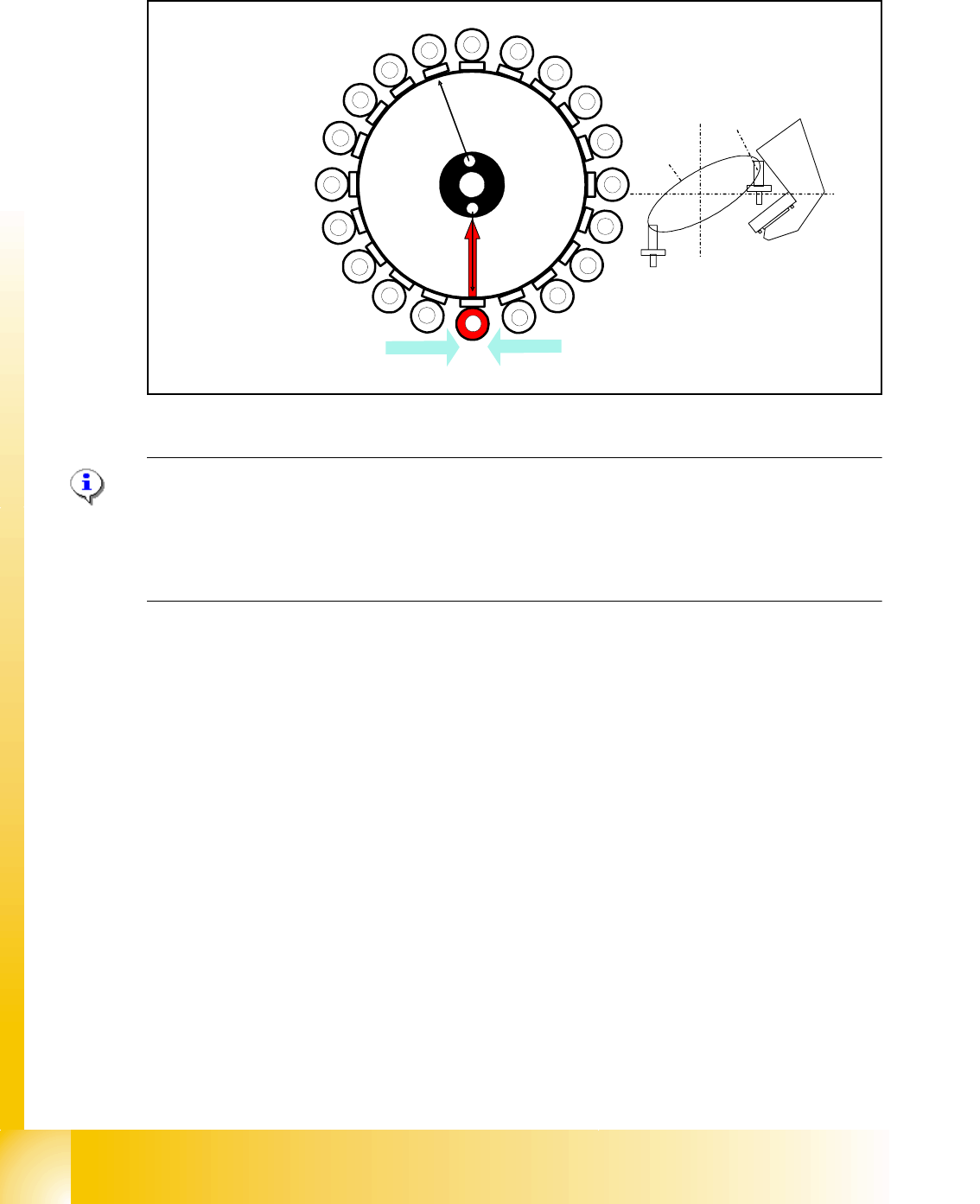
8.2.4 Z-Axis Reference Run
Fig. 8.2 - 4 Z-axis reference run
PLEASE NOTE:
Placement software startup initiates a comparison of the head EPROM Z-axis/star axis zero point
correction factor with that of the machine data. If there is variance, SITEST will offer a new cali-
bration of the zero point correction from the Z- and Star Axis, otherwise a normal Z-axis reference
run will begin.
The Z-Axis travels down to the zero point pulse of the incremental encoder. After the Z- Axis find
the zero point pulse, the zero point correction will be loaded. The Z- Axis travels to the zero point
correction value and the position counter is set to 0 digits.
1
2
3
4
5
6
7
8
9
10
12
11
13
14
15
16
17
18
19
20
Segment 1
Segment 11
S
t
a
r
p
o
s
i
t
i
o
n
CO- Camera
CO- Sensor
CO- Sensor
1 - 23
Student Guide SIPLACE X
Edition 09/2005 8 Collect&Place-Head 20
23
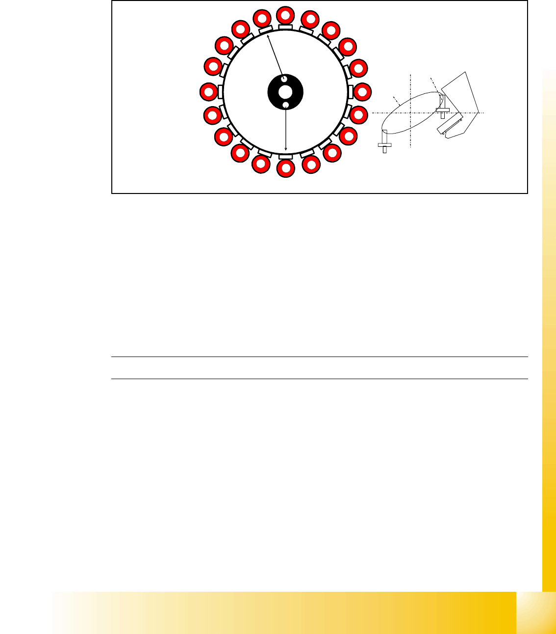
8.2.5 DP Axis Reference Run
The DP axis rotates the nozzle into the correct pickup angle and placement angle.
After component recognition has been performed, the DP axis turns the components into the cor-
rect placement angles and the determined correction angle from the vision system.
Fig. 8.2 - 5 DP axis reference run
– The machine start procedure: After the DP master firmware is loaded the DP drives are initial-
ized.
– After the reference runs for the Star axis and Z-axis have been performed, the segments rotate
into the 0° position.
– The DP axes can also be referenced independently of the star and Z axes.
– By determination of the largest amplitude of the Hall sensor becomes the 0° position of the noz-
zle in the factory (mechanically adjusted) and can't be changed.
The C&P head reference run has been successfully completed!
The gantry reference run will now be performed. For details, please refer to the chapter Gantry.
1
2
3
4
5
6
7
8
9
10
12
11
13
14
15
16
17
18
19
20
Segment 1
Segment 11
S
t
a
r
p
o
s
i
t
i
o
n
CO- Camera
1 - 24
Student Guide SIPLACE X
8 Collect&Place-Head 20 Edition 09/2005
24
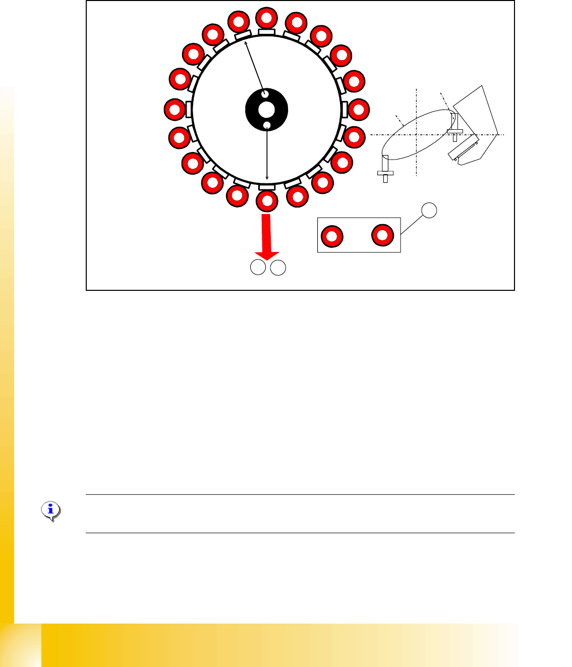
8.2.6 Vacuum Check Procedure
The vacuum check serves for control of soiled and damaged nozzles as well as for the check of
the nozzle types.
Fig. 8.2 - 6 Vacuum check procedure
– The gantry axes move the C&P head into the reject position to clean the nozzles before mea-
surement.
– The Star axes move in an anticlockwise direction and all cleaning functions are performed at
the same time, within one head cycle. (see Fig. 8.2 - 6).
(1) The DP drives rotate each segment into the 0° position.
(2) The digital pressure control valve now activates the air kiss for the reject position. The com-
ponents still on the nozzle will be rejected.
(3) The vacuum reference values (open/closed) are measured at the pickup/placement position
during the height reference run.
PLEASE NOTE:
In SIPLACE X machines, components are rejected in the pickup/placement position.
1
2
3
4
5
6
7
8
9
10
12
11
13
14
15
16
17
18
19
20
Segment 1
Segment 11
S
t
ar
p
o
s
i
t
i
o
n
CO- Camera
2
3
,
1
1
20
to