SiplaceX4_en.pdf - 第442页
1 - 10 S tudent Guide SIPLACE X 9 Component handling Edition 09/2005 10 9.2.2 Structure of the co mponent t able (X- t able) Fig. 9.2 - 2 COT (X- table) - side view 1. Moveable base 2. Feeder t able plate 3. T ape reels …
1 - 9
Student Guide SIPLACE X
Edition 09/2005 9 Component handling
9
9.2 Component changeover table
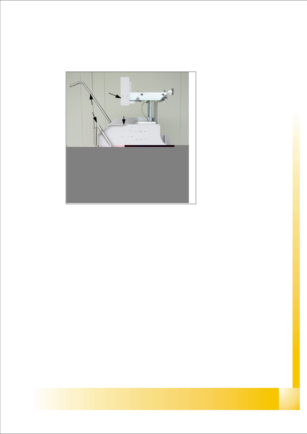
9.2.1 Structure of the component table (S- table)
Fig. 9.2 - 1 Component changeover table side view (S- table)
1. Moveable base
2. Feeder table plate
3. Communication unit;option splice detection unit is additional mounted below the communica-
tion unit
LED-Display Communication unit:
RED (Left) - Reset Communication unit
GREEN (Center) - Display Power supply --> OK
Yellow (Right) - Logic OK ( from Version-03:
Standard OFF, it flashes in the case
of the download of the firmware
4. Tape reels container
5. Tape waste container
6. Interface power supply, communication, safety loop
7. Sticker with an Identification number as alphanumeric Signs and as an barcode
8. Handles (for model 2 seperate to swifel)
9. Slot for set up lists on both sides
(1)
(8)
(3)
(4)
(5)
(5)
(2)
(6)
(9)
1 - 10
Student Guide SIPLACE X
9 Component handling Edition 09/2005
10
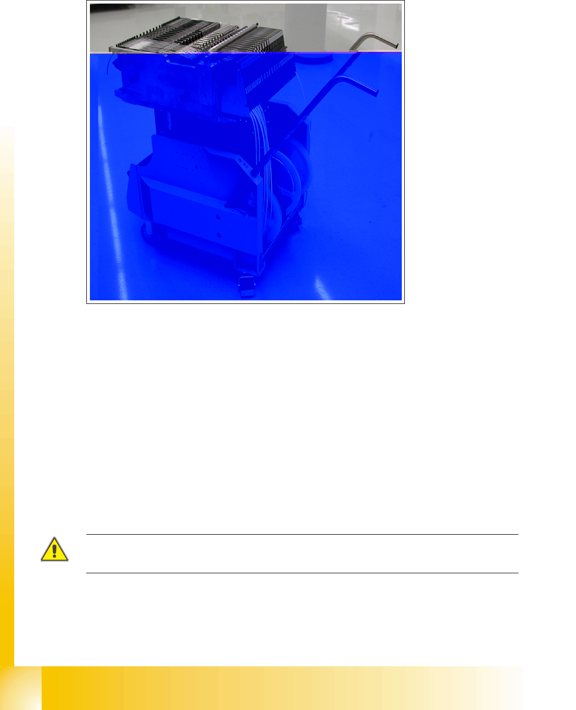
9.2.2 Structure of the component table (X- table)
Fig. 9.2 - 2 COT (X- table) - side view
1. Moveable base
2. Feeder table plate
3. Tape reels container
4. Tape waste container
5. Interface power supply, communication, safety loop
6. Sticker with an Identification number as alphanumeric Signs and as an barcode
7. Handles (for model 2 seperate to swifel)
– Slot for set up lists could be placed on both sides
ATTENTION :
Tracks which are not used has to be filled up with dummy feeder.
(1)
(2)
(3)
(4)
(4)
(5)
(6)
(7)
(7)
1 - 11
Student Guide SIPLACE X
Edition 09/2005 9 Component handling
11
9.2.3 Function description of the component changeover table
9.2.3.1 Docking
The docking process can only be perform when the machine is power on , compressed air is sup-
plied to the machine and the safety cover have to be closed.
For docking the COT move the table into the machine as far as possible, keep safety cover closed
and press the button (One hand operation). On the left and right from the empty tape duct are two
centering pins to center the COT for the final correct pick up position.
At docking procedure the component table plate raise (depend on machine and COT height) and
is pulled into the machine automatically. Two pneumatic cylinders with cam disks on the left and
right side of the COT move the trolley.
9.2.3.2 Undocking
When machine is running:
For undocking the COT open the safety cover and press the but-
ton 1. The component table is pushed out with two additional pneumatic cylinders at the left and
right of the empty tape duct. The COT is lowered by the cam disks. The COT electrical and pneu-
matic supply will be automatically disconnected from the machine.
When machine is OFF: Remove the COT for service without electrical and pneumatic power
supply -> Open the safety cover an pull out the COT on the handles.
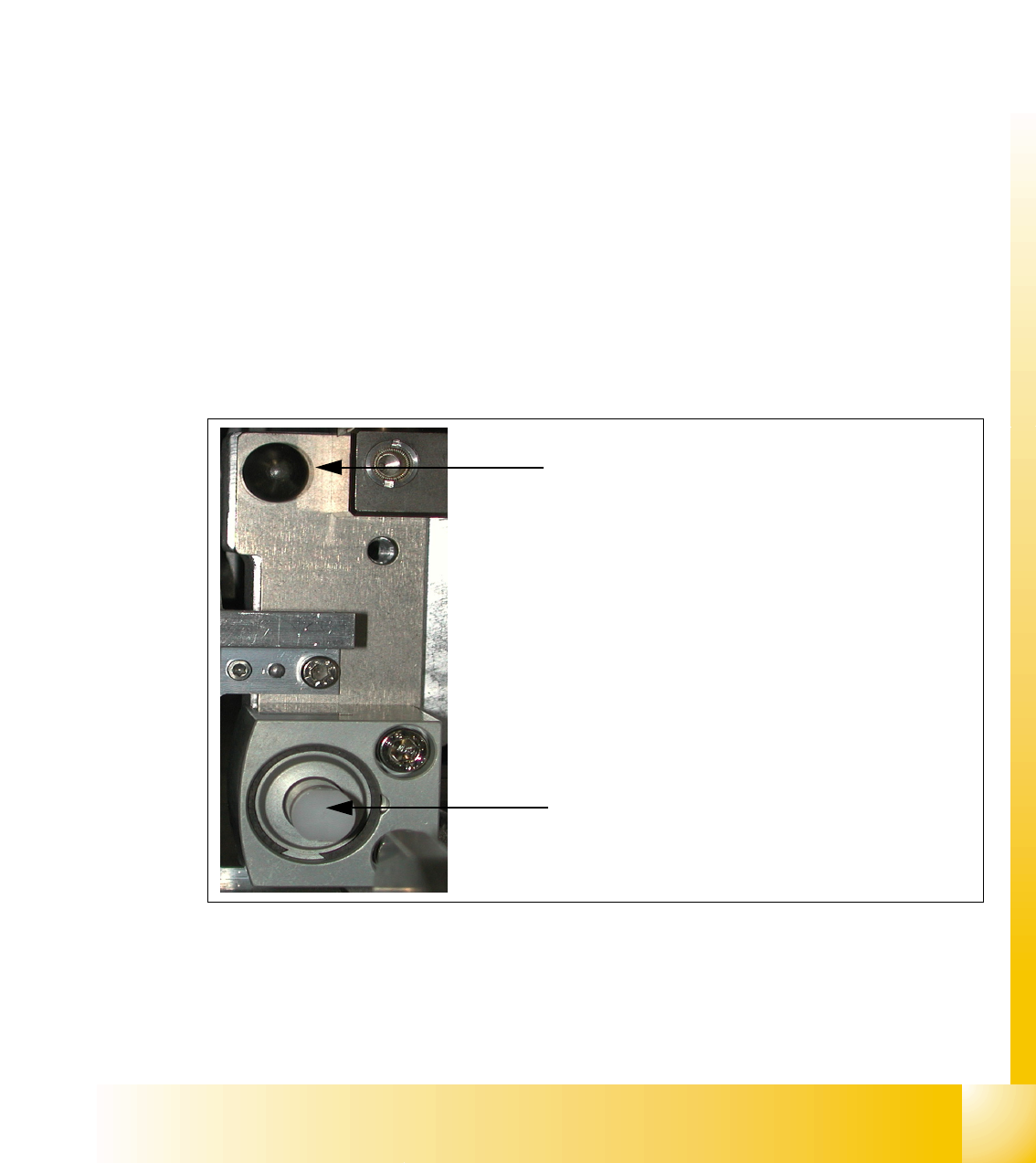
Fig. 9.2 - 3 Centering pin and pneumatic cylinder at the left and right of COT (X- and S- table)
Centering Pin for the table plate
Cylinder pushing out the COT at undocking