SiplaceX4_en.pdf - 第197页
1 - 3 S tudent Guide SIPLACE X Edition 09/2005 5 Gantry 3 5G a n t r y 5.1 Overview Gantry The gantries of the Siplace X ma chine consist of on e X- and one Y - axis. Both axes are d riven by a linear motor whic h is equ…

1 - 2
Student Guide SIPLACE X
Contents Edition 09/2005
2
5.5.3 Check dynamic Y- axis . . . . . . . . . . . . . . . . . . . . . . . . . . . . . . . . . . . . . . . . . . . . . . . 31
5.5.3.1 Test setup. . . . . . . . . . . . . . . . . . . . . . . . . . . . . . . . . . . . . . . . . . . . . . . . . . . . . . 31
5.5.3.2 Travel profile Y-axis C&P 20, C&P 6/12 head and Twin head in comparison . . 32
5.5.3.3 Positioning time tables Y-Axis depended on the head types . . . . . . . . . . . . . . . 33
1 - 3
Student Guide SIPLACE X
Edition 09/2005 5 Gantry
3
5Gantry
5.1 Overview Gantry
The gantries of the Siplace X machine consist of one X- and one Y - axis. Both axes are driven by
a linear motor which is equipped with an integrated temperature sensor. The Y-axis moves from
the right to the left side in positive counting direction if you look in transportation direction, the X-
axis moves from the the input conveyor to the output conveyer in positive counting direction. The
placement heads are mounted on the head plates of the respective X axis.
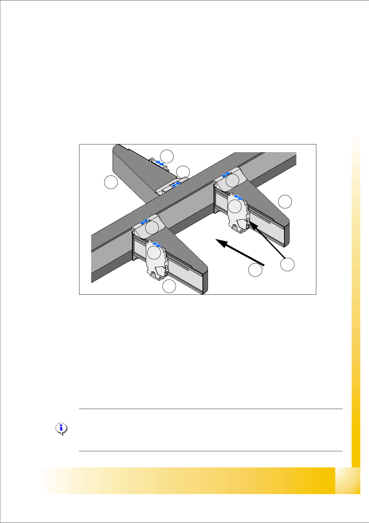
Fig. 5.1 - 1 Position of the gantries e.g. X3
Legend:
Note:
On the Siplace X and HF-Machines it is possible, that we use different kind of gantries. So
we recognize the gantry type with an Eprom and load automatically the right machine data
(CFK 02, CFK 04 or CFK 06).
G1Gantry 1 in PA1 G3Gantry 3 in PA2
X1 X-Axis, Gantry 1 X3 X-Axis, Gantry 3
Y1 Y-Axis, Gantry 1 Y3 Y-Axis, Gantry 3
G4Gantry 4 in PA 1
X4 X-Axis, Gantry 4 (T) Transportation direction
Y4 Y-Axis, Gantry 4 (TS)Temperature sensor on each head mounting plate
G4
G1
G3
Y4
Y3
Y1
X4
X3
X1
T
TS
1 - 4
Student Guide SIPLACE X
5 Gantry Edition 09/2005
4
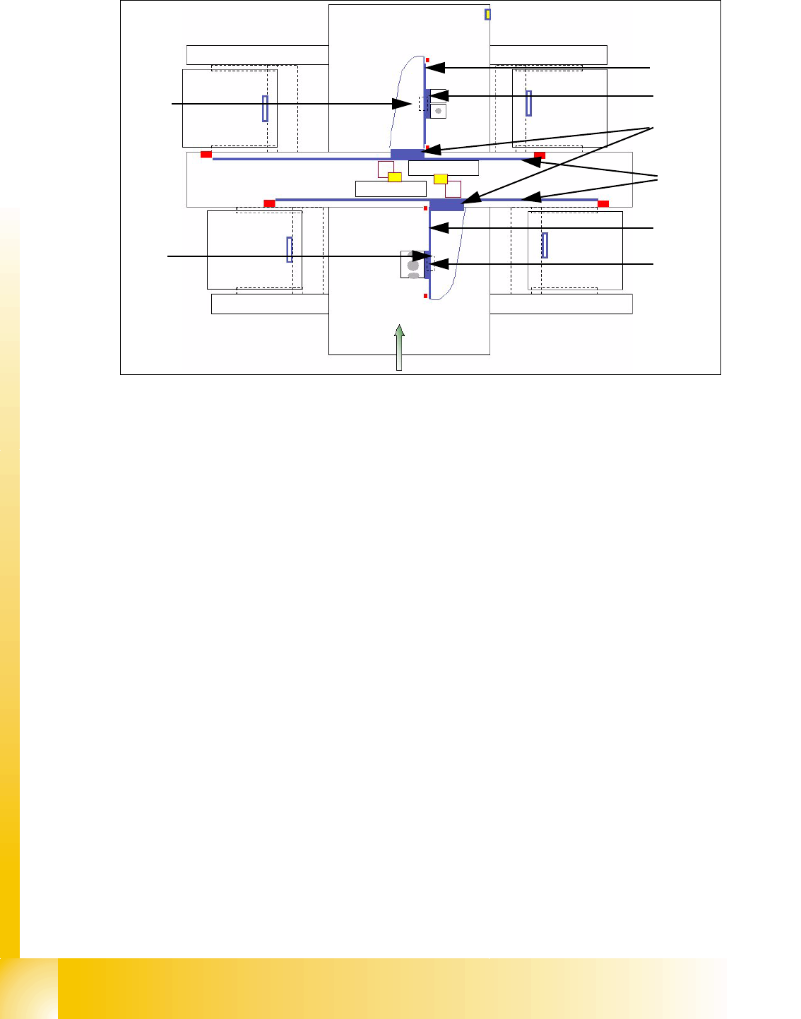
Fig. 5.1 - 2 Main parts at the "Gantries" e.g. X2
Legend
(1) Secondary part X-axis (Magnet) (2) Primary part X-axis (Linear motor)
(3) Primary part Y-axis (Linear motor) (4) Secondary part Y-Axis (Magnet)
(5) Secondary part X-axis (Magnet) (6) Primary part X-axis (Linear motor)
(7) PCB camera under the X-axis (8) PCB camera mounted under the gantry
1
2
3
4
5
6
7
8