SiplaceX4_en.pdf - 第348页
1 - 32 S tudent Guide SIPLACE X 7 T win-Head Edition 09/2005 32 7.4.8 Mechanical adjustment th e incremen t al encod er Z-axis Please Note: The increment al encoder on the Z-Axis must be adjust to a dista nce of 0,4 mm +…
1 - 31
Student Guide SIPLACE X
Edition 09/2005 7 Twin-Head
31
7.4.6.5 Check the "Air kiss" pressure
➠ Start SITEST.
➠ Move the gantry so that you can easily reach the nozzle of the Twin Head with one and the
keyboard with the other hand.
Please Note:
The value for the "Air kiss" pressure can be edited between 0 and 400 mbar. Standard value (only
for SITEST): 400 mbar 7
➠ Select "Twin Head"
Sitest: 7 ➠ Select "Head board functions" ==> Select the Twin module (segment)
➠ Switch "on" the air kiss.
➠ Close the nozzle of the appropriate Twin module (e.g. by sealing it with your finger tip).
➠ You can edit and modify the value for the forced air pressure or leave the standard value.
➠ Select "Measure pressure".
➠ The measured value should correspond (approx.) with the given value.
7.4.7 Calibrating the Twin- Head
During initial set-up or after replacement of a Twin module the Twin Head must be calibrated. The
Offset between TWIN Segment and PCB-camera center is meassured.
7
➠ Put the nozzles 517 by hand on the segments of the P&P modules.
➠ Make sure that the first nozzle from the garages are empty and depend on this the filling
level from the nozzle changer are edited, this is necessary for the calibration of the pick-up
height.
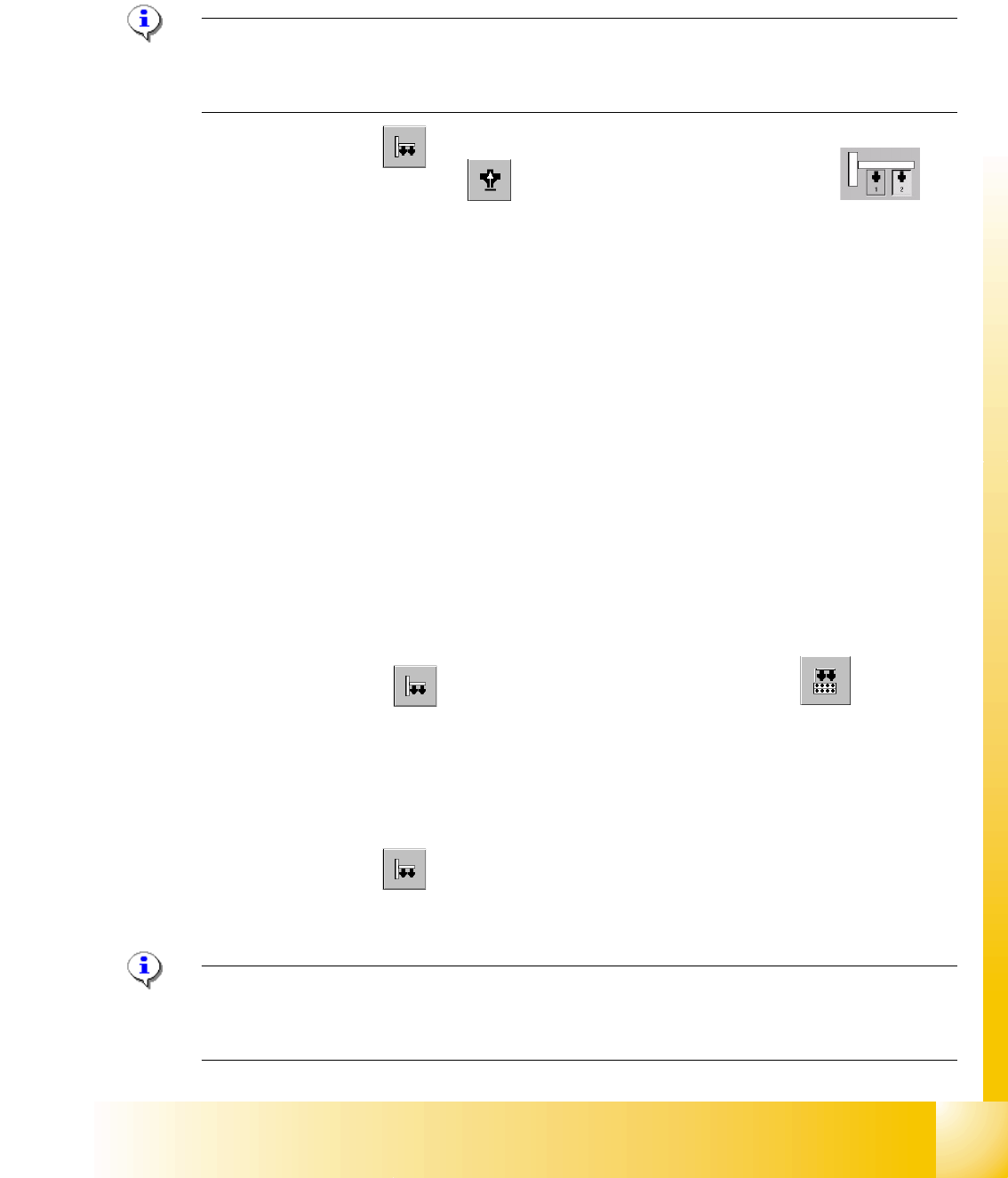
➠ Enter the nozzle "517" for both Twin modules as active nozzle on the Twin Head:
Sitest: 7 ==> Select "Twin Head" ==> Select "nozzle changer head functions" 7
7
==> Select the appropriate "segment" out of the list. 7
==> Select "Edit" ==> Select "517" and "accept". 7
==> Activate the checkbox "selected segment". 7
==> Select "Confirm exchange". 7
7
➠ Select "Twin Head" ==> Select "Calibrate machine"
==> Activate only "Twin Head" of the appropriate placement area.
==> Select "Start".
Please Note: The following points are calibrate automatically:
- MA-Zero point, PCB Camera, Calibration tool position, Head height, TH calibration Offset modul
1and 2, IC Camera, (option FC Camera) Nozzle changer. 7

1 - 32
Student Guide SIPLACE X
7 Twin-Head Edition 09/2005
32
7.4.8 Mechanical adjustment the incremental encoder Z-axis
Please Note:
The incremental encoder on the Z-Axis must be adjust to a distance of 0,4 mm +/- 0,1 mm to the
incremental scale. Please adjust the incremental encoder parallel to the incremental scale. For the
distance use a plastic feeler gauge of 0,4 mm.
After this adjustment of the incremental encoder you have to check the zero pulse and track sig-
nals (see chapter Tracksignals and Zeropulse).
7.4.9 Vision DC/DC Converter
The function of the Vision DC/DC converter is the power supply 42V for the stationary cameras.
The 42V are use for the illumination of the stationary cameras.
For changing the Vision DC/DC converter you have to do the following adjustments depend on
the location (Main-/ Sub- Distributor).
Tab. 7.4 - 1 Bypass, wire jumper on the connector of the DC/DC converter
Main Distributor
Bypass 1(wire jumper) 10 - 13
Bypass 2 (wire jumper) 11 - 12
Sub Distributor
Bypass 1 (wire jumper) 6 - 13
Bypass 2 (wire jumper) 4 - 12
1 - 33
Student Guide SIPLACE X
Edition 09/2005 7 Twin-Head
33
7.5 Nozzle changer
7.5.1 Nozzle changer for Twin- head
Die Siplace HF/HF3 and SIPLACE X machine will be delivered with a standard nozzle changer for
the twin head. This nozzle changer can hold up to 12 magazines. There are two types of magazine
available: standard magazines and magazines for special nozzles or grippers.
The nozzle changer may be installed depend on the configuration at location 1 and/or 3. The
nozzle changer consist of a standard modul with 3 nozzle holders two standard nozzles and one
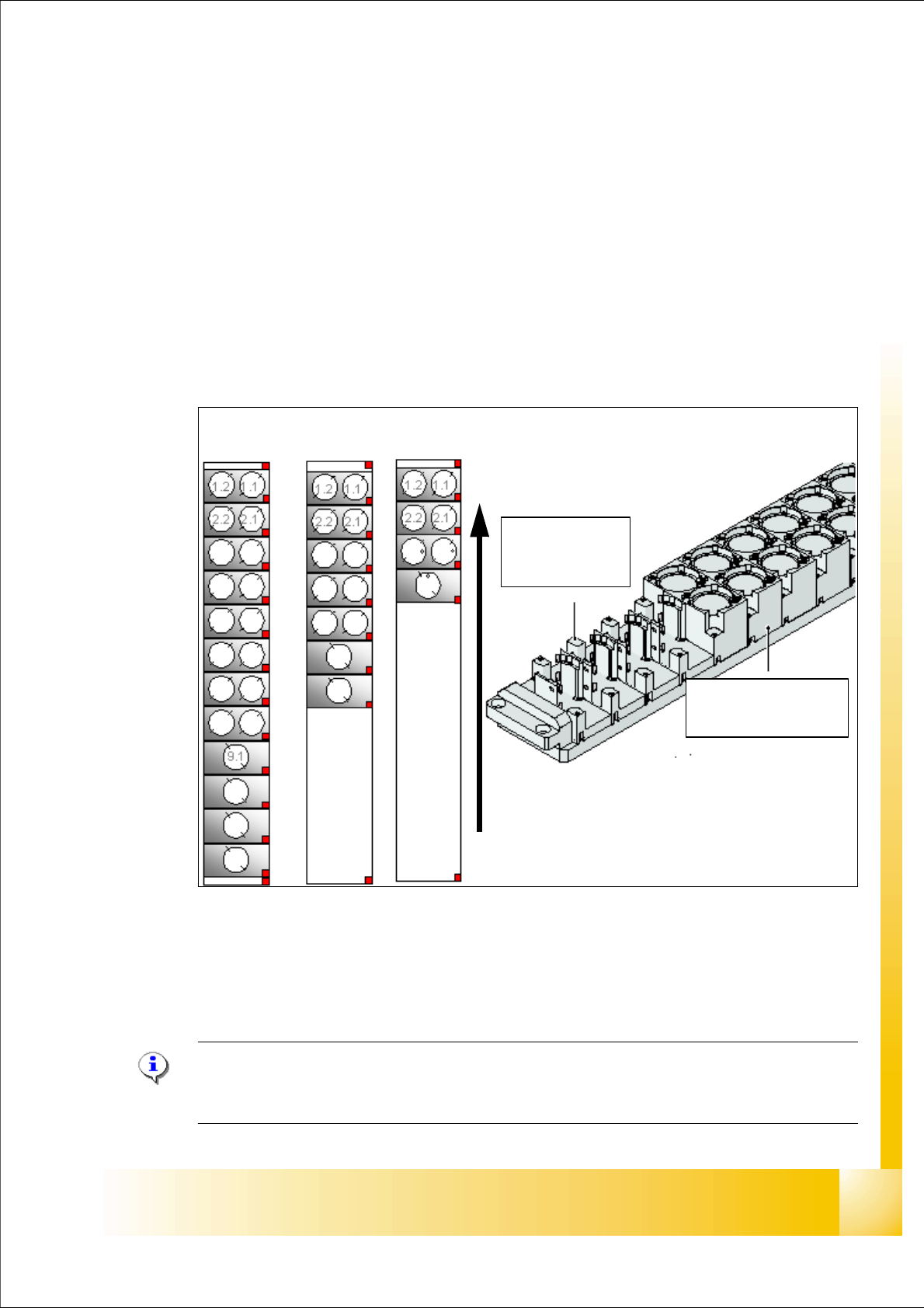
special nozzle or gripper. This configuration could be extended see Fig. 7.5 - 1.There are three
’Standard’ (504) magazine configurations.
Fig. 7.5 - 1 Nozzle changer configuration TWIN- head
(1) Standard-Nozzle changer
(2) Extended Nozzle changer
(3) Complete Nozzle changer
Please Note:
The magazines for standard, and special nozzles are freely configurable with the SW 505
or higher . 7
Transport direction
3
2
1
Magazine for
1 special nozzle
Magazine for 2
standard nozzles