SiplaceX4_en.pdf - 第87页
1 - 1 1 S tudent Guide SIPLACE X Edition 09/2005 3 Communication and Control 11 3.3.3 CAN Bus Concept SiplaceX4 The placement machine SIPLACE HF uses a bus system with 1 Mbit/s transmission rate.The CAN: Bus system begin…
1 - 10
Student Guide SIPLACE X
3 Communication and Control Edition 09/2005
10
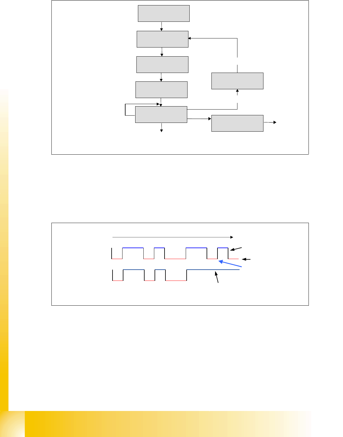
Fig. 3.3 - 9 flow chart bus arbitration
There are two bus states, called ’dominant’ and ’recessive’. The bus logic uses a ’Wired-AND’
mechanism, that is,
’dominant bits’ (equivalent to the logic level ’zero’) overwrite the ’recessive
bits’
(equivalent to the logic level ’one’).
Example: Arbitration with bit by bit detection of 2 members.
Fig. 3.3 - 10 CAN- bus arbitration with 2 members
waiting if bus is free
bit SoF
bus in receiving state
1st bit of arbitration
transmitted
compare transmitted bit
level with bus level
bus in error state
arbitration lost?
recessive bit on dominant bus state
all arbitration bits are transmitted,
send control field and data field
next bits
START: Any member
will send a message
11 10 9 8 7 6 5 4 3 2 1 0
recessive (logical high)
dominant (logical low)
member 1 wins arbitration here
member 2 looses arbitration here
and switch in receiving state
identifier member 1 1
Bit
identifier member 2 2
1 - 11
Student Guide SIPLACE X
Edition 09/2005 3 Communication and Control
11
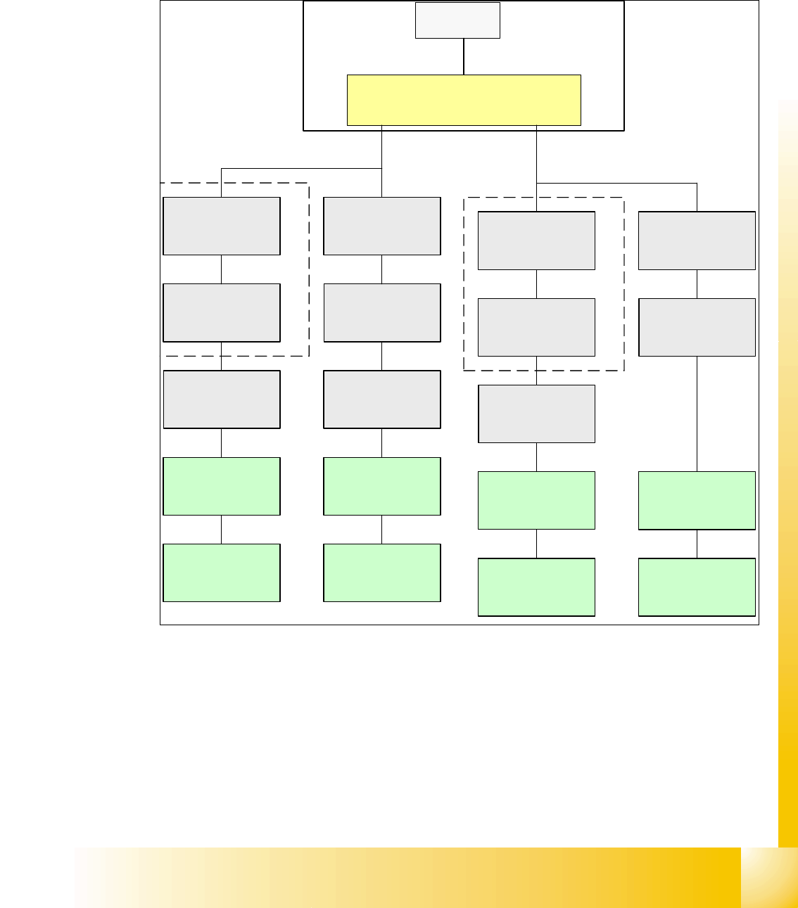
3.3.3 CAN Bus Concept SiplaceX4
The placement machine SIPLACE HF uses a bus system with 1 Mbit/s transmission rate.The
CAN: Bus system begin at the Communication board and is split in 2 path. Every path is termi-
nated by a 120 ohm terminator on the head board at the individual placement head.
.
Fig. 3.3 - 11 CAN Bus overview Siplace X4
SMP = Small Micro Prozessor
SMP BUS
MC
MC
Computer Unit
C
O
M
U
n
i
t
CAN Bus cable
PA 1
X6pn
Trailing Interface
Gantry 1
Transpor
t
Control unit
COT 1
Tape cutter
Axis unit
PA 1
CAN E/
A
Modu
l
CAN E/
A
Modu
l
Sektor
4
CAN E/
A
Modu
l
Sektor 4
CAN I/O
SUB Modul
Sector 4
Vision
Control unit
Sector 4
COT 4
Tape cutter
SUB Distributor Sector 4
Trailing Interface
Gantry 4
Head board(C500)
Gantry 4
Terminator
(120 OHM)
Head board(C500)
Gantry 1
Terminator
(120 OHM)
CAN Bus cable
PA 2
X7pn
Main Distributor Sector 2
COT 3
Tape cutter
Axis unit
PA 2
Vision
Control unit
Sector 2
CAN I/O
Main Modul
Sector 2
COT 2
Tape cutter
Trailing Interface
Gantry 2
Trailing Interface
Gantry 3
Head board(C500)
Gantry 2
Terminator
(120 OHM)
Head board(C500)
Gantry 3
Terminator
(120 OHM)
1 - 12
Student Guide SIPLACE X
3 Communication and Control Edition 09/2005
12
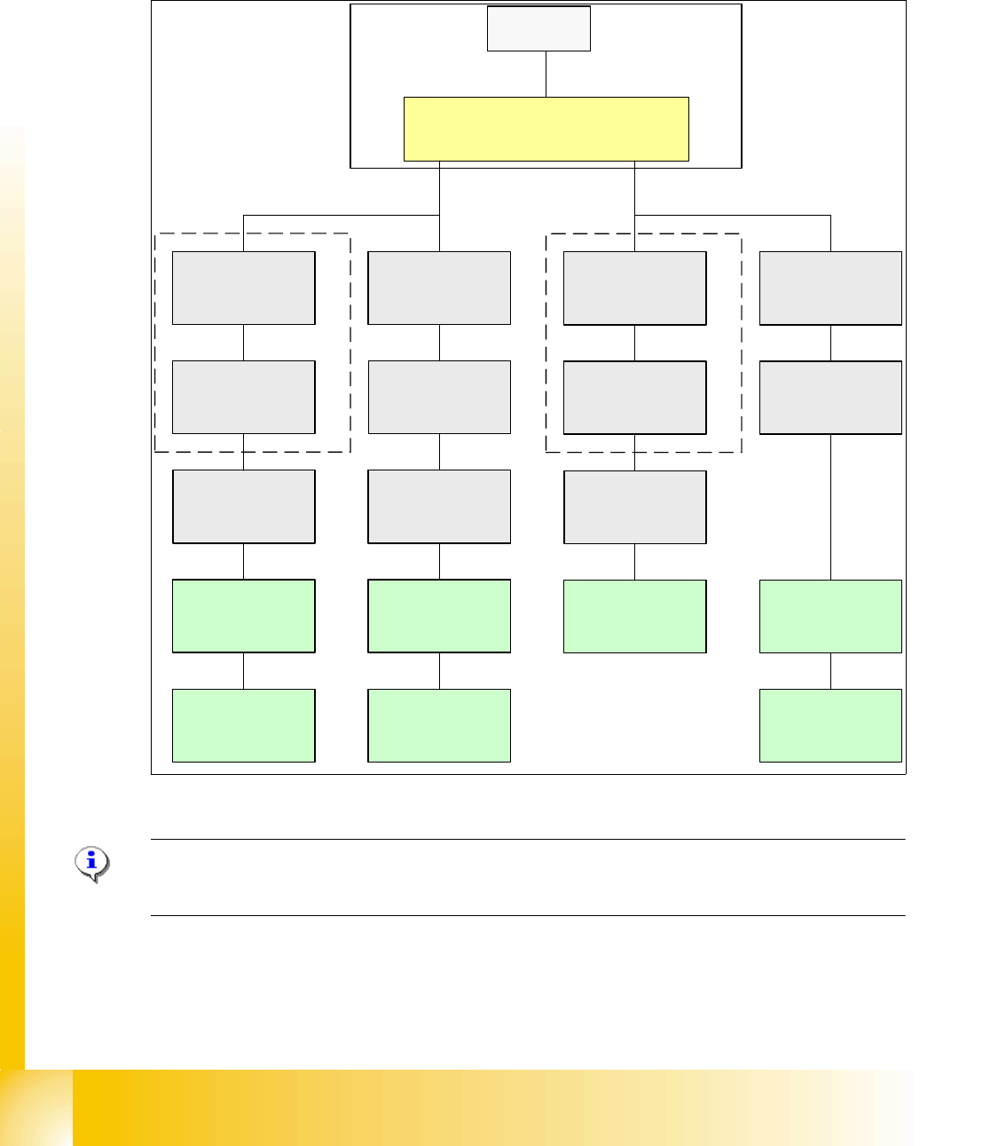
3.3.4 CAN Bus Concept SiplaceX3
The placement machine SIPLACE HF uses a bus system with 1 Mbit/s transmission rate.The CAN
Bus system begin at the Communication board and is split in 2 path. Every path is terminated by
a 120 ohm terminator on the head board at the individual placement head.
.
Fig. 3.3 - 12 CAN Bus overview Siplace X3
Note: When the Twin head is mounted, the switch for the terminator on the head board (C500)
have to be OFF. 3
SMP BUS
MC
MC
Computer Unit
C
O
M
U
n
i
t
CAN Bus cable
PA1
X6pn
Trailing Interface
Gantry 1
Transpor
t
Control unit
COT 1
Tape cutter
Axis unit
PA 1
CAN E/
A
Modu
l
Sektor
4
CAN E/
A
Modu
l
Sektor
4
CAN E/
A
Modu
l
Sektor
4
CAN I/O
SUB Modul
Sector 4
Vision
Control unit
Sector 4
COT 4
Tape cutter
SUB Distributor Sector 4
Trailing Interface
Gantry 4
Head board(C500)
Gantry 4
Terminator
(120 OHM)
Head board(C500)
Gantry 1
Terminator
(120 OHM)
CAN Bus cable
PA 2
X7pn
Main Distributor Sector 2
COT 3
Tape cutter
Axis unit
PA 2
Vision
Control unit
Sector 2
CAN I/O
Main Modul
Sector 2
COT 2 / MTC 2
Tape cutter
Terminator
120 Ohm
Trailing Interface
Gantry 3
Head board(C500)
Gantry 3
Terminator
(120 OHM)