SiplaceX4_en.pdf - 第103页
1 - 27 S tudent Guide SIPLACE X Edition 09/2005 3 Communication and Control 27 3.3.12 Communikation C&P 20 Head The TQM –modue l on the head interface C500 is communicate via the CAN Bus (1 M/Baud) to the Machine con…
1 - 26
Student Guide SIPLACE X
3 Communication and Control Edition 09/2005
26
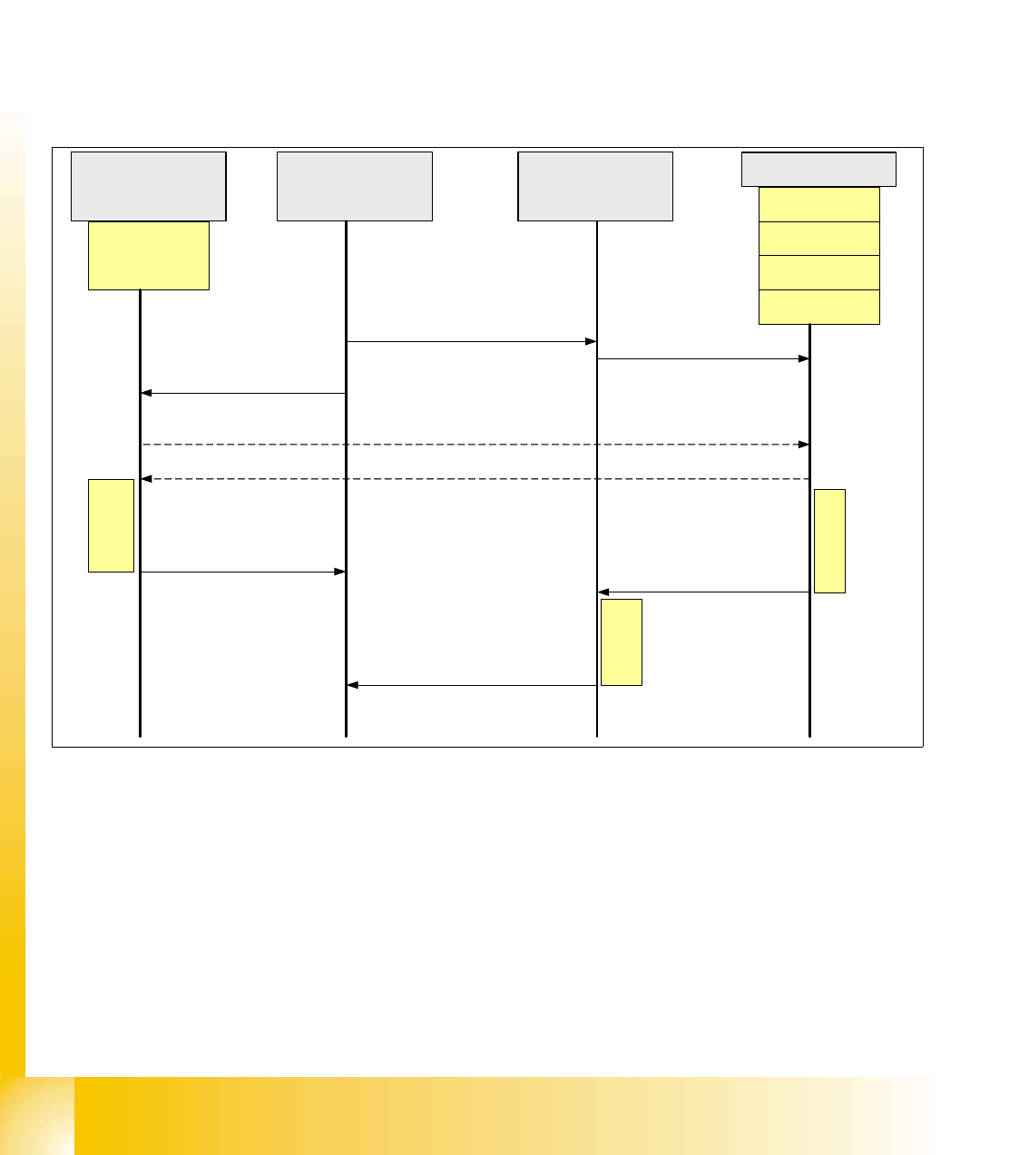
3.3.11.1 Communication during a image acquisition
The main communication between the vision system and machinecontroller is the transmission of
illumination values. These values, stored in the GF, are sent via CAN bus to the camera in ques-
tion. As soon as the camera should take the picture, the camera illumination is activated by a trig-
ger. From this moment on the row of LEDs which provide the different illumination levels light
dependant on the illumination value 0-255. This illumination value can have 0 = dark up to 255 =
bright. All illumination levels start lighting at the same moment. The value 0-255 determines the
length of the illumination time.
The maximum length of illumination is limited to 6 ms.
Fig. 3.3 - 21 Time sequence from up to down for the Communication Image acquisition
Cameras
Illumination
Controller
Machine controller
(MC)
Stationcomputer with
Visionsoftware
Prepare
CAN Bus
Illumination
(ca. 6ms)
PCB-Camera
FC-Camera
IC-Camera
Component
Camera
Start Image acquisition
(Illumination values)
Prepare Flash
(illumination)
Hardware Signal
(Trigger)
Visionboard(LP,BE)
Vision Control unit ,
(IC,FC)
Ready message
to the MC
Signal "Ready for
Image aquisition"
CAN Bus
Image
interpretation
Image
acquisition
Ready message
to the VISION SW
Result
"Image interpretation"
1 - 27
Student Guide SIPLACE X
Edition 09/2005 3 Communication and Control
27
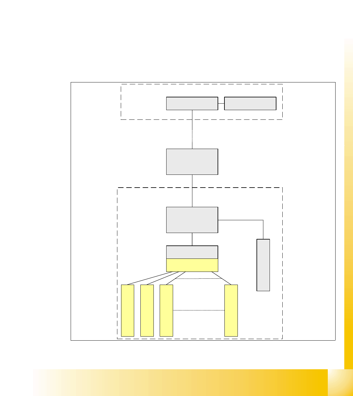
3.3.12 Communikation C&P 20 Head
The TQM –moduel on the head interface C500 is communicate via the CAN Bus (1M/Baud) to the
Machine controller.
The communication from the head interface to the C&P20 head is carried out with an additional
CAN Bus. Which sed the data with 125KBaud. (in Future 500kBaud)
The 20 DP - axes are controled via the „DP- Master" on the motherboard. So the machine CAN
Bus send 4 commands:
– Start the DP axis after Pick up/Placement (Pick up angle/Placement angle)
– Start the DP axis after Vision (Correction angle)
– Wait DP axis before Vision (Position commando not allowed)
– Wait DP axis before Pick up/Placement (Position commando not allowed)
Fig. 3.3 - 22 CAN-Bus controlled head function on the C&P 20 head
Computer Unit
Head processor
C500
COM Board
Vacuum/air kiss
generator
Machine- CAN Bus
(1MBaud)
Head- CAN Bus
(125KBaud/
500KBaud)
DP Master
Motherboard
C&P 20 Head
DP - drive 20
DP - drive 1
DP - drive 2
DP - drive 3
Intermediate
distributor
MC
1 - 28
Student Guide SIPLACE X
3 Communication and Control Edition 09/2005
28
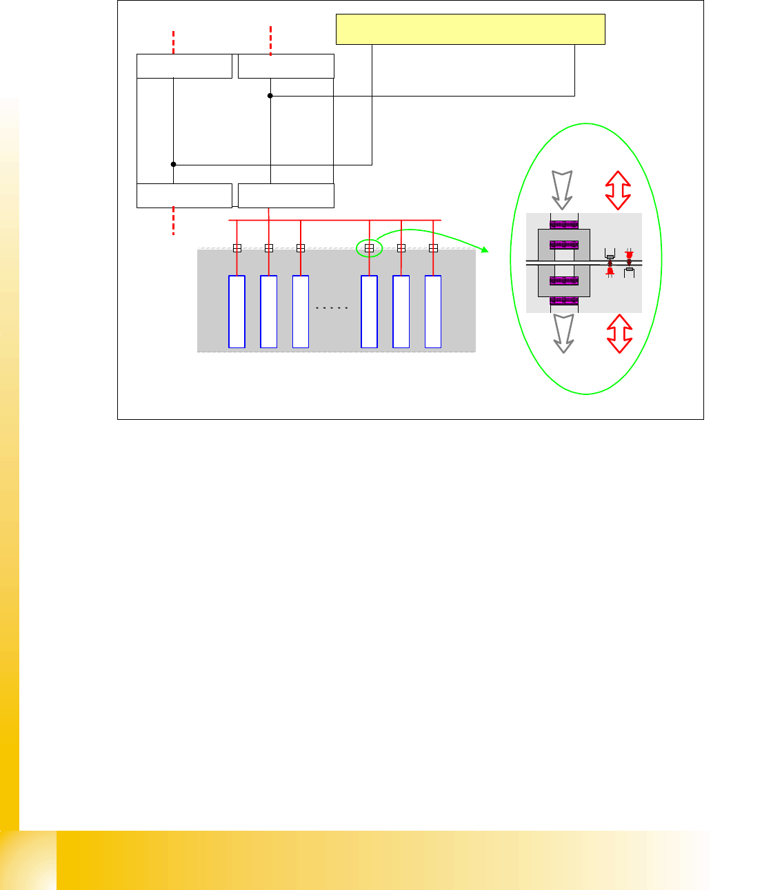
3.3.13 Communication X-Feeder
The Communication between the Feeder Control unit (FCU) and each X- Feeder is carried out via
a CAN bus. This CAN bus is only responsible for the communication between FCU and X-Feeder
and machines CAN bus controlled the "Feeder Can Bus".
Fig. 3.3 - 23 Communication X-Feeder
The data and power supply from the FCU to each feeder is contactless.
SIPLACE
X-Serie
Feeder
Feeder
Feeder
Feeder
Feeder
Feeder
Feeder-CAN Bus
BE-Wagen
(COT)
Power Data
Power Data
Machine CAN Bus
FCU Location 1
C
O
M
U
n
i
t
x
6
p
n
x
7
p
n
FCU Location 2
FCU Location 3FCU Location 4