SiplaceX4_en.pdf - 第339页
1 - 23 S tudent Guide SIPLACE X Edition 09/2005 7 T win-Head 23 7.4.2 Parameter and Calibrations 7.4.2.1 Overview calibration step s and p arameter in the Sitest Fig. 7.4 - 4 Overview calibration steps and parameter Plea…
1 - 22
Student Guide SIPLACE X
7 Twin-Head Edition 09/2005
22
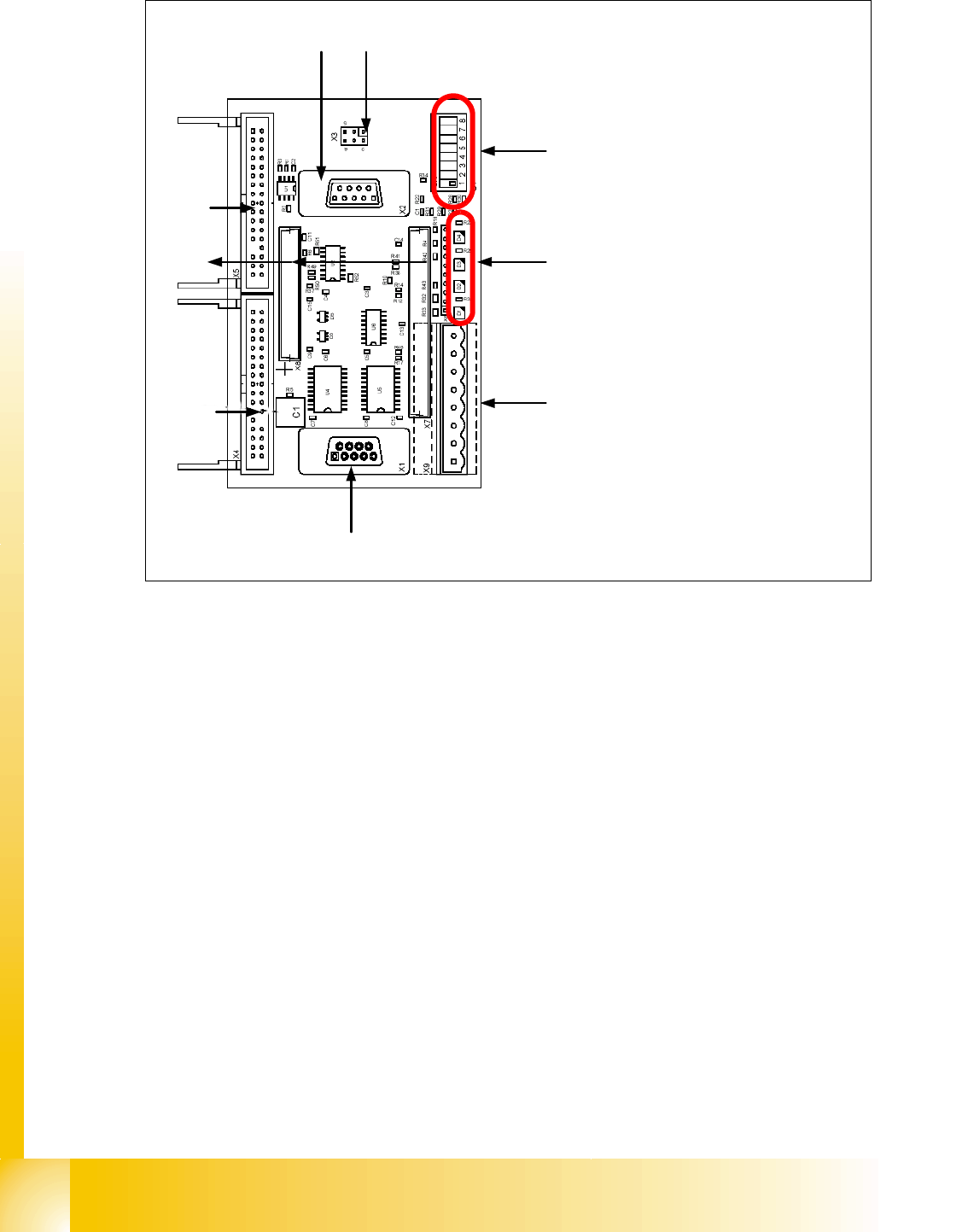
Fig. 7.4 - 3 Vision control board IC camera
1. Connector for FC Camera illumination
2. Connector for IC Camera illumination
3. Service connector
4. LED‘s (downwards D4 - D1)
– + 5 V / -15 V / +15 V / +40 V
5. DIP Switch
6. Connector CAN Bus
7. Power supply Vision control board
Connector for DC/DC converter (Section2)
for DC/DC distributor (section 4)
8. Connectors for CAN Bus Processor 16 Bit
9. Flash signal (not used for Siplace Vision)
1
6
3
4
5
2
7
8
9
to 5)DIP-Switch
(1) CAN- Terminator
(2) RESET
(3) Bootstrap
(4) TEST
(5) P1 Address -Switch
(6) P0 Address -Switch
(7) CAN - ID 1
(8) CAN -ID 0
1 - 23
Student Guide SIPLACE X
Edition 09/2005 7 Twin-Head
23
7.4.2 Parameter and Calibrations
7.4.2.1 Overview calibration steps and parameter in the Sitest
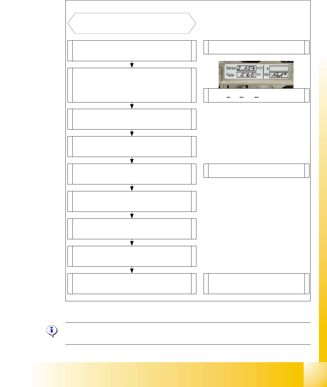
Fig. 7.4 - 4 Overview calibration steps and parameter
Please Note: This steps are necessary during the first initial setup or a replacement of the TWIN
Head modul. The detail description are explained on the following pages.
Type in the parameters for the strain
gages(Force sensor), spring pre-tension,
and the standard values for the Z-axis
(max.-,min.- travel range and ZPC*) and
ZPC* D-axis .
Switch ON the machine and start
the Sitest
Note: Don`t start the reference run
Start the reference run D-axis
Calibrate D-axis
Start the reference run Z-axis
Determined the zero point correction in
the Menu "Calibration functions"
Precondition for further calibration:
Entire reference run
Precondition:Twin head Modul is
mounted and electrical and pneumatic
connections are fixed.
Compensation the vacuum control
system in the Menu "Head board"-->
"Zero calibration for pressure regulator"
Calibrate closed vacuum in the Menu
"Twin head-->Calibration functions"
Check the air kiss and the pressure
tightness of the vacuum system in the
Menu "Twin head-->Head board"
Calibrate Twin head and nozzle changer
in the Main menu
"Sitest --> All Heads and Cameras"
Note: The first garages have to be
empty at the nozzle changer and the
the fill level must be correct.
Check the zero calibration of the vacuum
control system in the Menu "Head board"
* ZPC: Zero Point Correction.
1 - 24
Student Guide SIPLACE X
7 Twin-Head Edition 09/2005
24
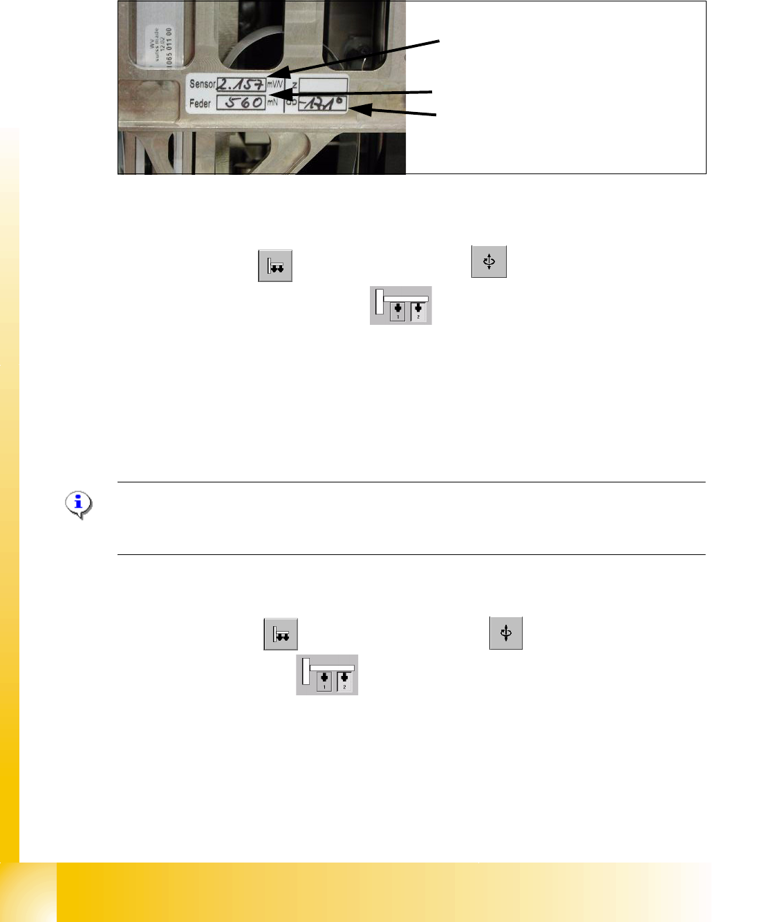
7.4.3 Parameter Twin- Head
You find a label with parameters for the TWIN-head module which must be entered in the Sitest
during initial set-up or after replacement of a TWIN-module.
7
Fig. 7.4 - 5 Label with parameter for TWIN-head modul
Parameter force sensor and spring pre-tension 7
Sitest: 7
➠ Select "Twin Head" ==> Select "axis functions"
➠ Select the appropriate Twin module)
➠ Select the checkbox "Z-axis".
➠ Select "Parameter..." and enter the values
"Force sensor calibration value" in [mV/V].
This value is always smaller than 3.0 [mV/V] .
and "Spring pre-tension" in [mN]. This value is between 300 and 700 [mN] .
➠ Wrong settings for the twin module will result in inaccurate placement or pick-up force (1 bis
15N).
Please Note:
The adjusting screw (fine thread) for the spring pre-tension MUST NOT be adjusted - otherwise a
replacement of the P&P module might be necessary.. 7
Zero point correction (ZPC) D-Axis 7
Sitest: 7
➠ Select "Twin Head" ==> Select "Axis functions"
==> Select the Twin module
7
==> Aktivate the checkbox "D-axis" 7
==> Select "Positions..." 7
==> Deaktivate the checkbox "digits" 7
==> Enter the ZPC value in 1/100 degrees into the 2. row " ZPC from the label" and select "ac-
cept".
7
Sensor (Parameter for strain gauges,force
sensor)
Feder (Spring pre-tension)
dp (zero point correction D-axis)