SiplaceX4_en.pdf - 第344页
1 - 28 S tudent Guide SIPLACE X 7 T win-Head Edition 09/2005 28 7.4.6 Zero calibration for pressure regulator on the T win- Head The vacuum generator is a p art at the T win head and creates the vacuum and air kiss for t…
1 - 27
Student Guide SIPLACE X
Edition 09/2005 7 Twin-Head
27
7.4.4.1 Manual Calculation of the ZPC D-axis
In case of an unknown ZPC of the D-axis the ZPC can be calculated and edited manually: 7
Sitest: 7 Select "Twin Head" ==> Select "axis functions"
==> Select the P&P module
==> Activate the checkbox "D-axis"
==> Select "Positions..."
==> Set the zero point correction to "0" .
➠ Perform an axis reference run for the D-axis.
➠ Deactivate the D-axis of the P&P module at the axis card.
➠ Turn the nozzle manually into the "zero position":
The drilling on the calibration nozzle must show to the outside (not the center) of the machine
and the nozzle must be aligned parallel to the PCB conveyor.
➠ In order to display the angle of the D-axis, activate the checkbox "Z-axis" and reactivate
"D-Axis" subsequently.
➠ Enter the shown value for the D-axis as zero point correction value.
➠ Activate the D-axis of the P&P module at the axis card.
➠ Perform an axis reference run for the D-axis.
➠ Check the alignment of the nozzle:
The drilling on the calibration nozzle must show to the outside (not the center) of the machine
and the nozzle must be aligned parallel to the PCB conveyor.
➠ Don’t forget to perform the calibration of the D-axis, see chapter 7.4.4.
7.4.5 Calibrate head height
With this Menu the Z-axis zero point correction is determined.
Please Note: Please make sure that 517 nozzle are on the TWIN-Head
The ZPC, maximum and minimum positions for the Z-axis will be set correctly after this calibration
step.
Sitest: 7 ➠ Select "Twin Head" ==> Select "calibration functions"
Select the TWIN-module
==> Select "Calibrate head height".
1 - 28
Student Guide SIPLACE X
7 Twin-Head Edition 09/2005
28
7.4.6 Zero calibration for pressure regulator on the Twin- Head
The vacuum generator is a part at the Twin head and creates the vacuum and air kiss for the pick
up and placement process. The zero calibration for the vacuum generator should be make for the
first set up on customer side and after exchanging the vacuum generator or twin module.
7
If you don‘t calibrate the vacuum generator you use wrong thershold values for open and closed
vacuum and it could be you get error messages about "No component on the nozzle or nozzle is
dirty".
7
With the aid of the zero calibration we positioning the motor of the vacuum generator into a middle
or neutral position, so that you don‘t have any vacuum or air kiss on the nozzle.
7
7.4.6.1 Zero calibration vacuum generator
➠ Start the SITEST.
7
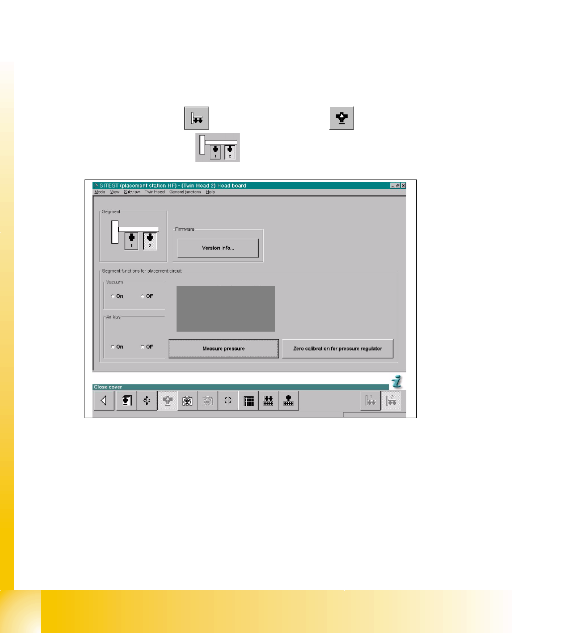
Sitest: 7 ➠ Select "Twin head" ==> Select "Head board"
➠ Select the "Segment"
Fig. 7.4 - 6 SITEST Functions Head board
➠ Close the nozzle of the appropriate Twin module (e.g. by sealing it with your finger tip).
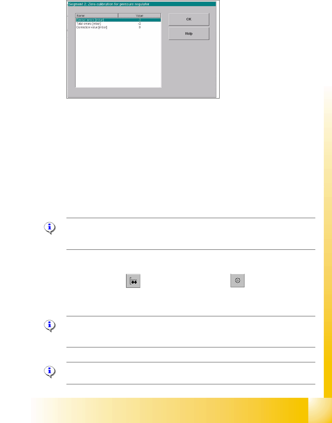
==> Select "Zero calibration pressure regulator"
The following display appears and show the correction values.
1 - 29
Student Guide SIPLACE X
Edition 09/2005 7 Twin-Head
29
7
Fig. 7.4 - 7 Correction values after zero calibration
➠ Press "OK".
The correction value will be accepted - now the reference value equals the ambient pressure.
7.4.6.2 Check the Zero calibration of the vacuum generator
Sitest: 7
Select "Twin head" ==> Select "Head board" ==> Press the button "Measure pressure"
If you check the zero calibration the preconditions are "Vacuum is OFF" and "Air kiss is OFF"
(siehe Fig. 7.4 - 6).
Please Note
The pressure deviation to the ambient pressure in the case of 0 - mbar calibration should not
exceed for ± 10 mbar. 7
7.4.6.3 Calibrate closed vacuum
Sitest: 7
➠ Select "Twin Head" ==>Select "calibration functions"
==> Select Sie "Calibrate closed vacuum"
Please Note:The value for "closed vacuum" will be measured automatically for both Twin mod-
ules.
In the dialog window the former and the new values are shown. 7
Please Note:
The indication "closed vacuum" equals "Threshold value closed" in SITEST. 7