SiplaceX4_en.pdf - 第51页
1 - 27 S tudent Guide SIPLACE X Edition 09/2005 2 Overview 27 2.2.9 Siplace Vision The new , digit a l Siplace V ision system helps sa tisf y customer demands for greater speed, flexibil- ity and robustness Advantages of…
1 - 26
Student Guide SIPLACE X
2 Overview Edition 09/2005
26
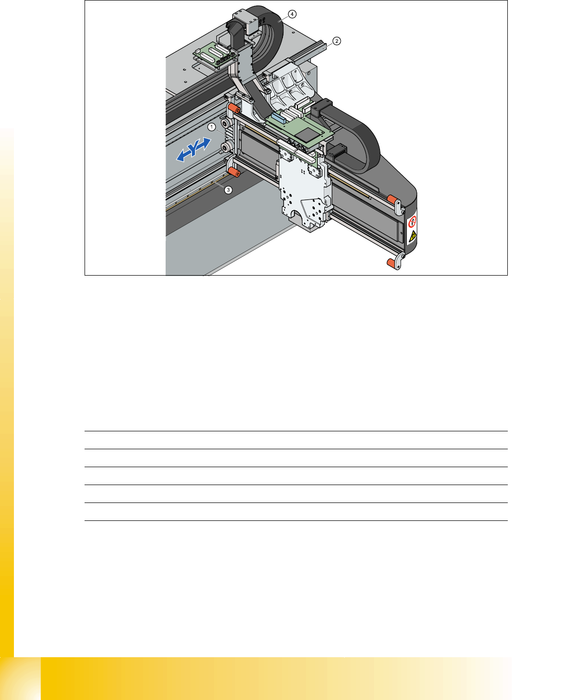
2.2.8 Construction of the Y-axis
2
Fig. 2.2 - 14 Construction of Y-axis
Key The Y-axis consists of the following main modules:
The Y-axis is driven by a linear motor. The secondary part of the drive consists of a permanent
magnet and is fixed to the machine frame. The primary part is screwed to the gantry arm (X-axis).
Y-axis technical data 2
(1) Linear drive permanent magnet (2) Linear incremental encoder
(3) Linear guide (4) Y-axis trailing cable
Drive direct, linear drive
Max. speed 2,5 m/sec.
Gantry travel range 1430 mm
Length incremental encoder 1850mm
Resolution 1 µm
1 - 27
Student Guide SIPLACE X
Edition 09/2005 2 Overview
27
2.2.9 Siplace Vision
The new, digital Siplace Vision system helps satisfy customer demands for greater speed, flexibil-
ity and robustness
Advantages of the digital Vision system:
– Robust and fast calculation algorithms
– Flexible measurement procedures
– Self-learning graphical user interface
– Supports geometrical description of components at the machine.
– State-of-the-art digital camera hardware
– Homogenous illumination of camera visual field and components
Each C&P head has its own digital component camera. For twin heads, a stationary camera is
installed in the machine.
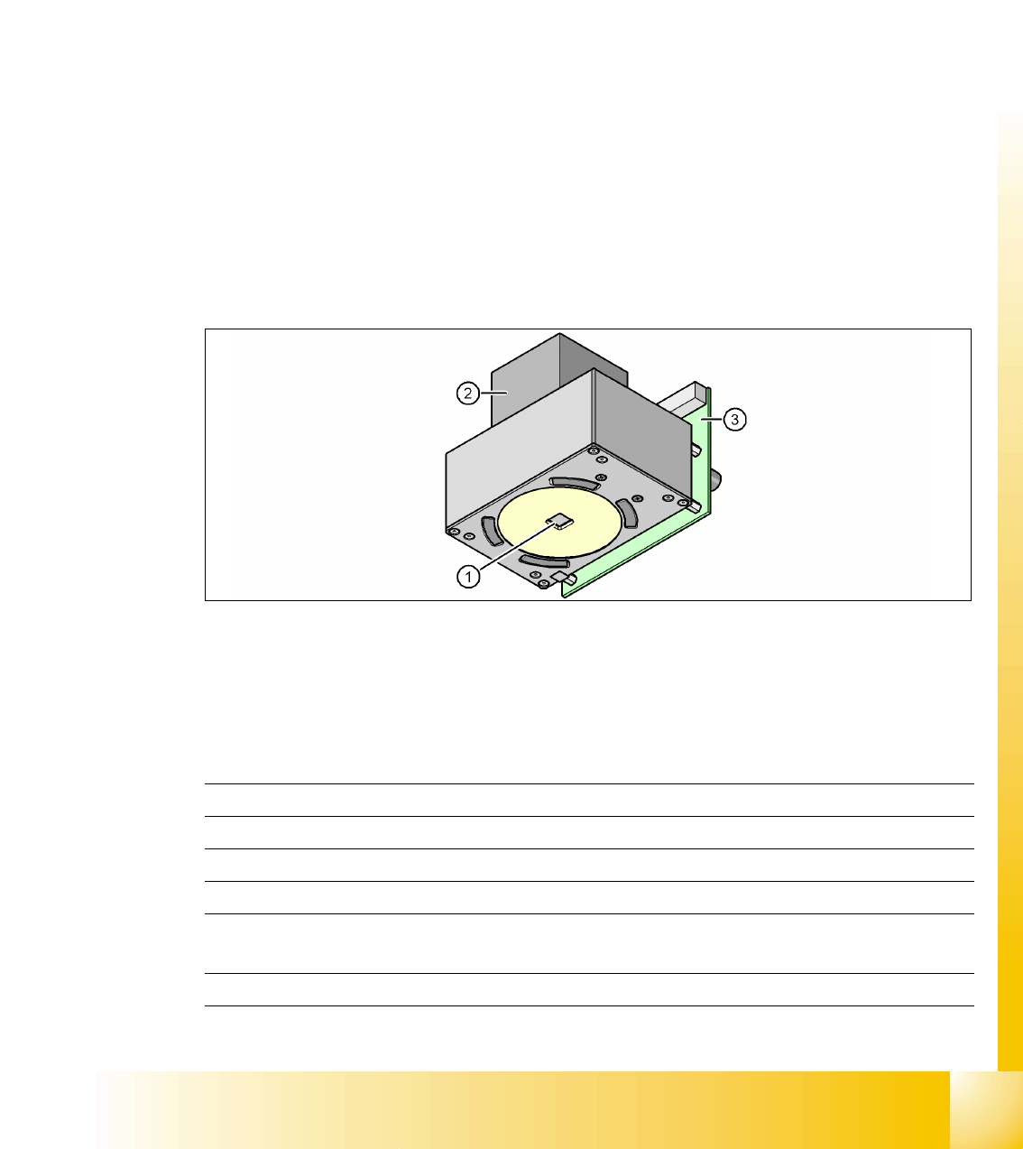
2.2.9.1 Digital PCB Camera (Multicolor)
2
Fig. 2.2 - 15 PCB camera under the gantry (X-axis)
(1) Camera optics
(2) Camera amplifier
(3) Illumination control for blue, infrared and white LEDs in the various illumination levels
Technical data 2
2
PCB fiducials max. 3 per placement program
Field of view (FOV) 5.7 mm x 5.7 mm
Illumination type from above
Resolution 9.8µm/pixels
Fiducial size 0.3 to 2.5 mm (up to 3.0mm, depending on PCB trans-
port tolerance.)
Camera type .sst 24.sst
1 - 28
Student Guide SIPLACE X
2 Overview Edition 09/2005
28
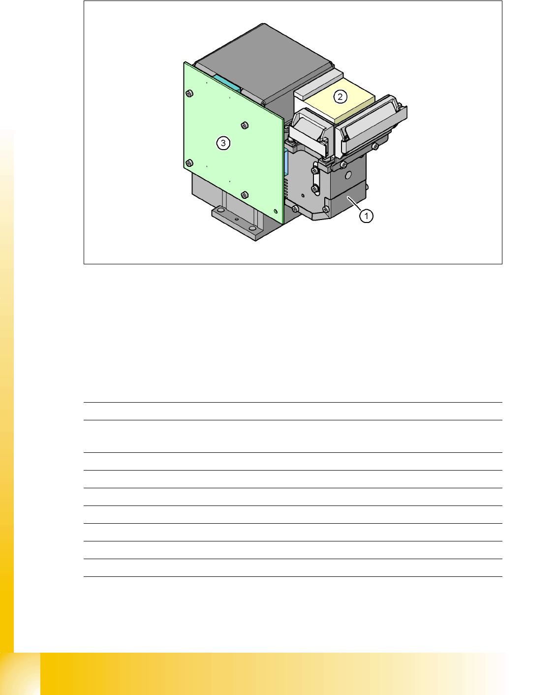
2.2.9.2 Digital Component Camera for 12-Segment C&P Head
2
Fig. 2.2 - 16 Component camera as standard on the 12-segment collect&place head
2
1. Component camera optics and illumination
2. Camera amplifier
3. Illumination control
Technical data 2
2
Option: Digital camera from 6 segment DLM 2 head (camera type 29.sst) for 0201 placement. 2
Component size 0.5 mm x 0.5 mm to 18.7 mm x 18.7 mm
Component shape 0402 to PLCC44 incl. BGA, µBGA, Flip-Chip,
TSOP, QFP, PLCC, SO to SO32, DRAM
Minimum lead pitch 0.5 mm
Minimum ball pitch 0.45 mm
Minimum ball diameter 0.25 mm
Field of view (FOV) 24.5 mm x 24.5 mm
Illumination type from above (4 levels programmable)
Resolution 50µm/pixels
Camera type .sst 28.sst