SiplaceX4_en.pdf - 第303页
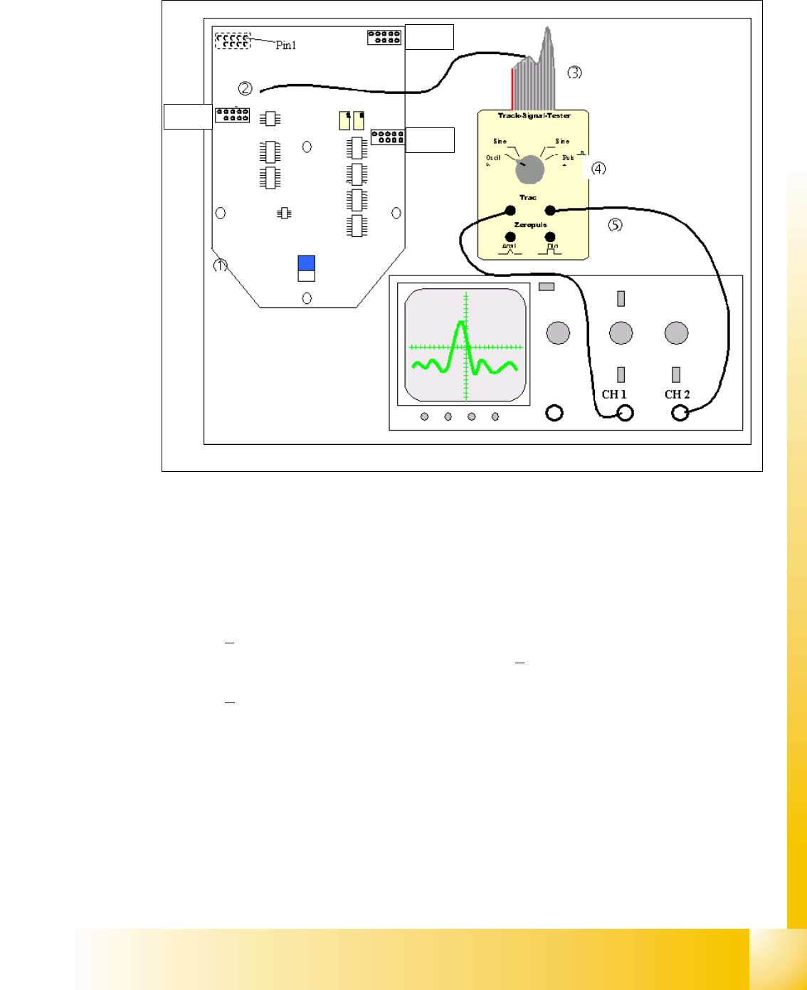
1 - 75 S tudent Guide SIPLACE X Edition 09/2005 6 Coll ect &Place-Head 6/12 75 6.6.2.2 T est set up Fig. 6.6 - 2 General test set up to check the track signals X13 = Z-Axis X15 = S tar-A xis X16 = DP-Ax is 6 Connecto…

1 - 74
Student Guide SIPLACE X
6 Collect &Place-Head 6/12 Edition 09/2005
74
6.6.1.1 Overview positioning time 12 segment C&P head
6
6.6.1.2 Overview positioning time 6 segment C&P head
6
6.6.2 Track signals head axes
The track signals undertake a meaning function in the case of the new drive concept of the HF
machine. They are responsible for the exactly and precise positioning of the axes and are used
as only response of the closed-loop control system so that the track signals have an important
influence on dynamics of the axes.
6.6.2.1 Overview
6
Axis Mode / Distance Positioning time
Star Axis continuous run / 1 Star step 46ms +/-3ms
Z absolute, free space / 685 digits 24ms, -1ms
Z
Light barrier bottom, into Calibration tool pocket / ca.
685 digits 24ms +/-3ms
DP 100 digits 13ms +/-3ms
DP 3600 digits 43ms +/-3ms
Table 6.6 - 1 Positioning time 12 segment C&P head DLM2
Axis Mode / Distance Positioning time
Star
Axis continuous run / 1 Star step 70ms +/-3ms
Z absolute, free space / 685 digits 30ms +/-3ms
Z
Light barrier bottom, into calibration tool pocket / approx.
685 digits 30ms +/-3ms
DP 200 digits 38ms +/-3ms
DP 7200 digits 85ms +/-3ms
Table 6.6 - 2 Positioning time 6 segment C&P head DLM2
Axes Mechanical settings Oszilloscope diagram
Star 6 25x: Resolution 1/1000° 6 digital track signal amplitude 3,6V
pp
6
Z 6 nothing 6 digital track signal amplitude 3,6V
pp
6
DP 6 DP-axis Incremental encoder adjustment
to the glass scale (segment)
1,5 mm 6
digital track signal amplitude 3,6V
pp
6
Tab. 6.6 - 3 Adjustments Oscilloscope
1 - 75
Student Guide SIPLACE X
Edition 09/2005 6 Collect &Place-Head 6/12
75
6.6.2.2 Test set up
Fig. 6.6 - 2 General test set up to check the track signals
X13 = Z-Axis
X15 = Star-Axis
X16 = DP-Axis 6
Connector description of the connectors X13, X15, X16:
The track signals of the head axes can only be measured as digital signals i.e. the transformation
of the analogous track signals into digital track signals occurs directly in the incremental encoder.
X13
X16
X15
1. Ground 2. Track A
3. Track A
4. Ground
5. Track B 6. Track B
7. +5V 8. Track N
9. Track N
10.Pin removed
1 - 76
Student Guide SIPLACE X
6 Collect &Place-Head 6/12 Edition 09/2005
76
6
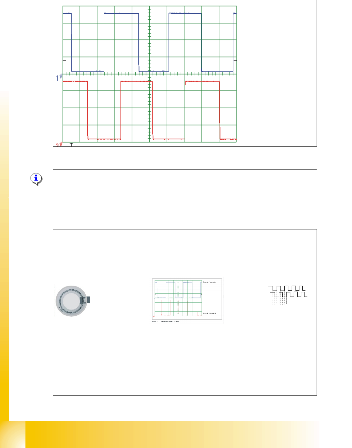
Fig. 6.6 - 3 Digital track signals head axes
Please Note:
The pulse width is dependent on the speed, the phase location is dependent on the direction. 6
6.6.2.3 Preparation of the track signals for control the star axis as example
Spur A / track A
Spur B / track B
Track Signal - Star Axis (not adjustable)
Digital Track Signal A, B and N
(zero
pulse) sent to Interm. Distributor Board.
Sensor
3.6 Vpp
Multiplication and Digitalization
of the Analogue
Track Signals A, and B
by
the
Digital Access
Controller on theInterm. Distributor Board.
(Multiplication by a factor of 25 for Digital Conversion)
Rotor
Scale
(3600 ticks / 360° of scale)
Incremental scale on the
DLM 2 C&P head
Transfer the track signals
to the axis board A 363
with VC3
12341234…..
Axis board A 363 with
VC3
Final Multiplication at Control
Unit Axis Decoder
.
(Multiplication by factor of 4)
End Result:
(3600) x (25) x (4) =
360.000 pulses / 360
°
Therefore ....
1° =1000 digit
1 digit = 0.001°