SiplaceX4_en.pdf - 第450页
1 - 18 S tudent Guide SIPLACE X 9 Component handling Edition 09/2005 18 9.2.5.4 Additional feeder fixation The Feeder-Fixing is an additional mechanical safety precau tion. It prevent to move the fe eder at the component…
1 - 17
Student Guide SIPLACE X
Edition 09/2005 9 Component handling
17
9.2.5.3 Compressed air supply for Bulkcase feeder
Bulkcase feeder need for operation pressure air supply. So this pressure air supply is offered as
an option .
it is easy to mount. First remove the bung (Pos. 1) at pressure air hose in the feeder table (Pos.
2). Than the pneumatic supply for the bulck case feeder is mounted (Pos. 3) with 2 screws DIN
912, M8x20 (Pos. 4) on the component table (Pos. 2). At the rear side of the airkiss supply unit
are feeder clamps mounted (Pos. 5). This clamps keep the Bulkcase-feeder down correctly sealed
to the pressure air supply.
Fig. 9.2 - 11 Unit for bulkcase feeder
Legend
(1) Bung at component table 2. Componnent table
3. Pressure air supply for Bulkcase-Feeder 4. Screw DIN 912, M8x20
5. clamps for bulkcase feeder
1 - 18
Student Guide SIPLACE X
9 Component handling Edition 09/2005
18
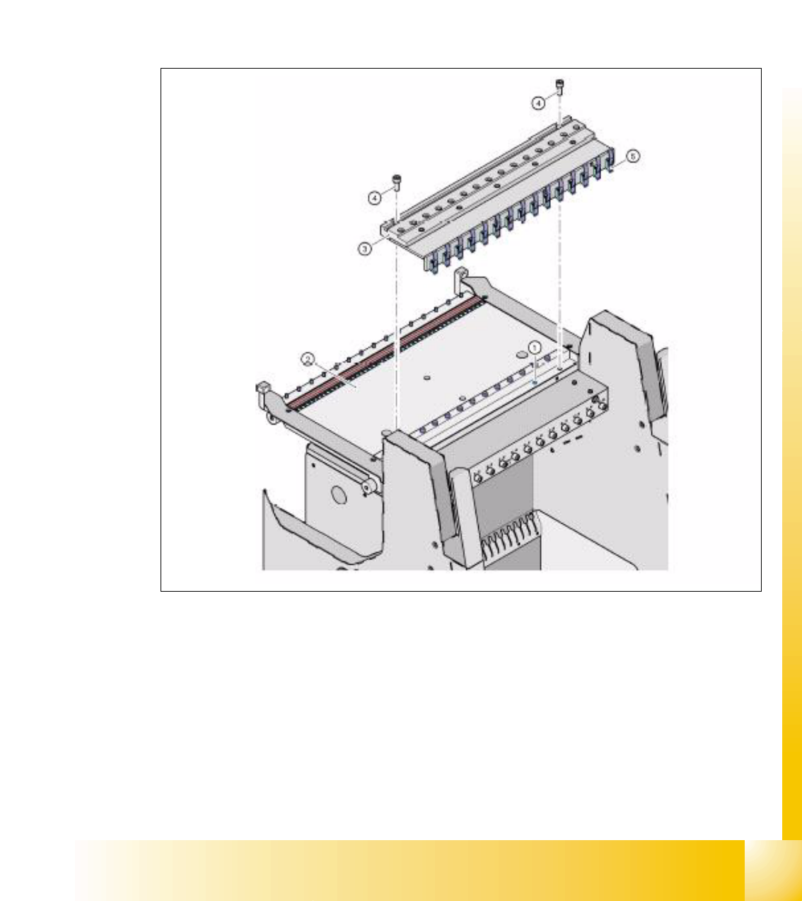
9.2.5.4 Additional feeder fixation
The Feeder-Fixing is an additional mechanical safety precaution. It prevent to move the feeder at
the component table by accident. It exclude a head crash risk with a wrong positioned feeder.
The feeder-fixation is is mounted on the front side of the component table. The clamp lock the front
feeder stand. Forthe full set up of this option each feeder table get such a clamp.
Fig. 9.2 - 12 COT feeder fixation
Legend
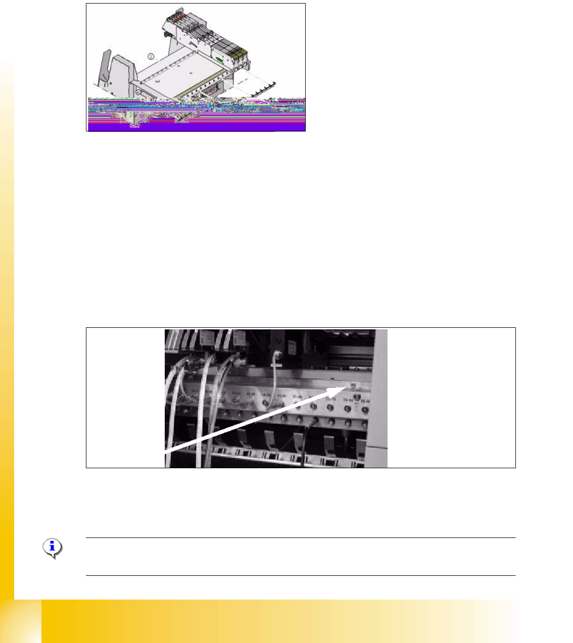
9.2.5.5 Additional Communication unit for splice detection
An additional communication unit for the option Traceability with splice detection is necessary.
Splice detector is connected to this communication unit. The communication unit sent an informa-
tion to the SC software when a splice is detected at the component tape.This set the new fill level
for this component automatically.
Fig. 9.2 - 13 Additionally communication unit for splice detection
(1) The additionally communication unit is mounted together with the communication unit on the
component changeover table.
NOTE : X- splice- sensor are mounted directly behind the pick up position of the X- feeder and
they communicate via feeder CAN- bus --> machine CAN- bus with the station software.
(1) Feeder fixation 2. Component table
1
1 - 19
Student Guide SIPLACE X
Edition 09/2005 9 Component handling
19
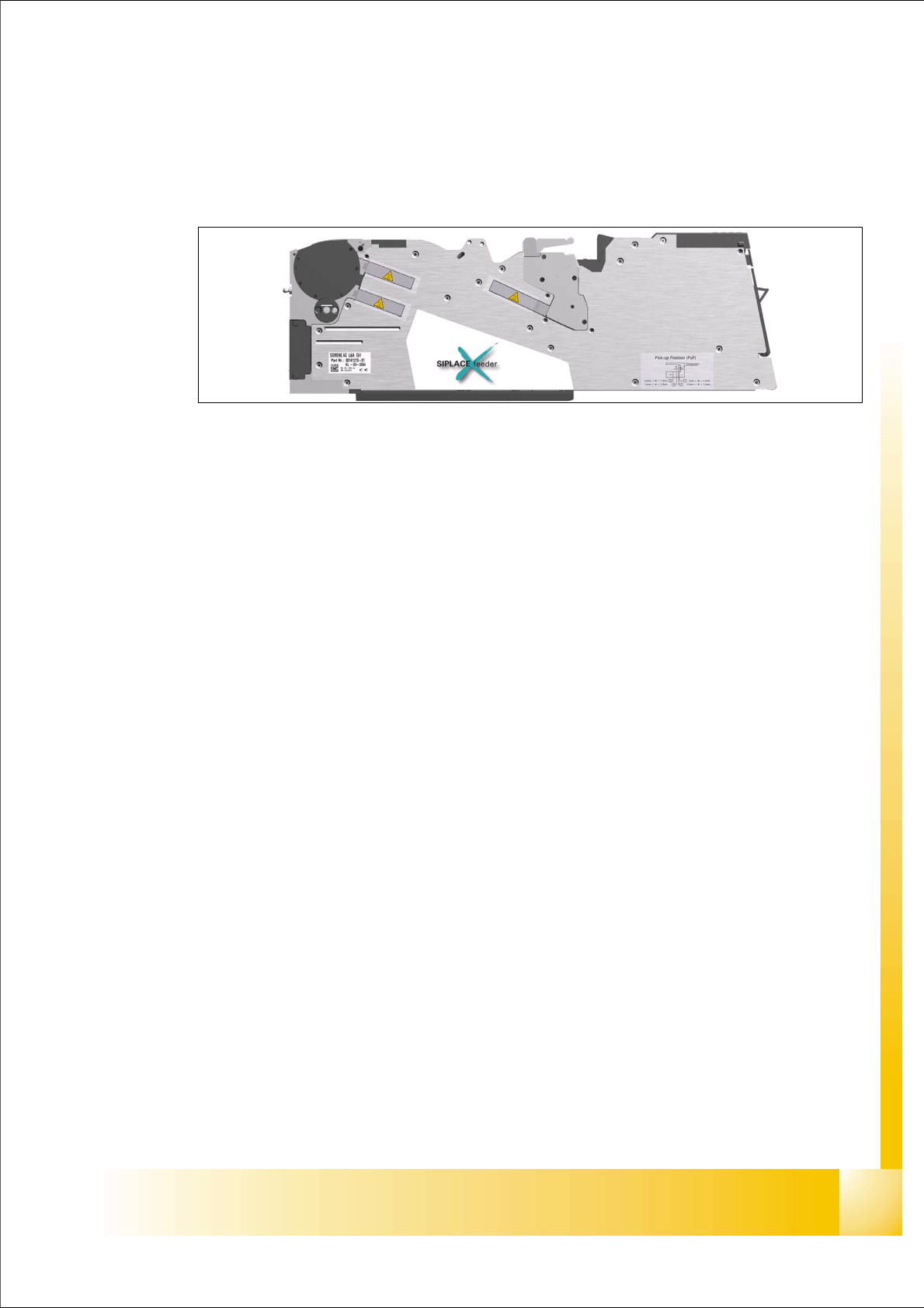
9.3 X- Feeder
9.3.1 General
Fig. 9.3 - 1 main view - X- Feeder
Performance : 9
– Increased demand for speed at C&P20- head (Communication, dynamics 40ms for 4mm),
Feeder should not limit placement (communication, transport)
Precision : 9
– Designed for smallest components currently on the market
Reliability: 9
– Reliable drive system, "Closed loop" drive regulation, new mechanical interface, new electrical
interface, brushless DC- motors, optimised gear
Flexibility : 9
– Different pitches adjustable, "Hot- swaping" possible, Upgrade per Firmware- Download pos-
sible with station software, Adaptable to "problematic tapes", free step width, variable speed
profiles
Usability : 9
– Single track feeder, Tape loading, Interface to operator, Integrated Splice recognition (op-
tional), Able to handle sticky tapes (optional PSA kit (pressure sensitive adhesive)), no con-
nectors and cables, operator panel
Intelligence : 9
– Unique feeder- ID, Management data (cycles, power up hours, errors,...), Object data are
stored in set- up control data base
Robustness : 9
– No "on mechanical end stops" --> controlled movement of the transport