SiplaceX4_en.pdf - 第503页
1 - 35 S tudent Guide SIPLACE X Edition 09/2005 10 Modular conveyor 35 10.3.3 LED display on the TSP 301 conveyor control PCB-Handling inte rface pr evious station track1 with diagnosis LED’ s PCB-handling 10 PCB-Handlin…
1 - 34
Student Guide SIPLACE X
10 Modular conveyor Edition 09/2005
34
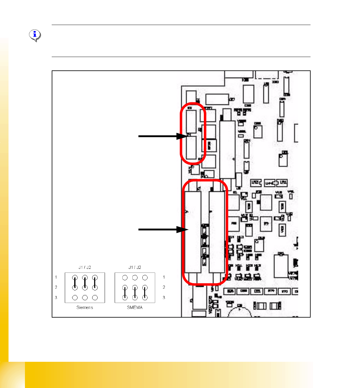
10.3.2 Transport control board TSP 301 with Siemens interface(Option)
Following modification are necessary for using the Siemens interface:
(1) Application: no modification.
(2) JumperJ1 / J2: have to change (see below).
(3) Disconnect the connector X3 and X4 on the TSP 301!
(4) Connect the Siemens interface cable on the connector X1 and X2.
Please Note:
The 10 pin Locking-Clip connector of the SMEMA-connector have to disconnected from the
TSP301! Destruction of the TSP board!
Fig. 10.3 - 2 TSP 301 SMEMA --> Siemens
➠ 10 pin connector for SMEMA- Interface
X3 Previous Station
X4 Next Station
➠ Connector for Siemens-Interface
X1 Previous Station
X2 Next Station
1 - 35
Student Guide SIPLACE X
Edition 09/2005 10 Modular conveyor
35
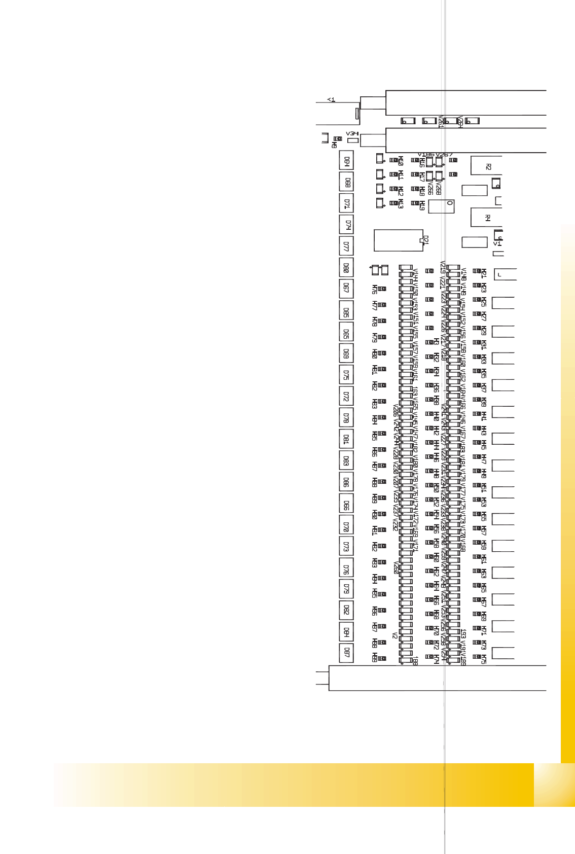
10.3.3 LED display on the TSP 301 conveyor control
PCB-Handling interface previous station
track1 with diagnosis LED’s PCB-handling
10
PCB-Handling interface following station
track1 with diagnosis LED’s PCB-handling
10
10
PCB-Handling interface previous station
track2 with diagnosis LED’s PCB-handling
10
PCB-Handling interface following station
track2 with diagnosis LED’s PCB-handling
10
10
LED description see Fig.11.3.4 10
10
Fig. 10.3 - 3 Conveyor control TSP 301

1 - 36
Student Guide SIPLACE X
10 Modular conveyor Edition 09/2005
36
10.3.3.1 Assignment table: LEDs on the TSP 301 conveyor control
Display I / O LED assignment
H1 / F1-F5 Fuses F1-F5 Power supply 34V
H2 / F6 Fuse F6 Power supply 24V
H4(ao) Initializing / control error
H5(ao) CAN bus 1, active
H6(ao) Flashing: Program running
H7(ao) CAN bus 2, active (optional)
H9 Out Interference loop
H14 IN Siemens interface for upstream station
H15 IN Siemens interface for downstream station
H20 IN Lifting table, placement area 1: Fork light barrier A
H21 IN Lifting table, placement area 1: Fork light barrier B
H22 IN Lifting table, placement area 2: Fork light barrier A
H23 IN Lifting table, placement area 2: Fork light barrier B
H24 IN Laser light barrier, placement area 1: Receiver
H25 IN Laser light barrier, placement area 2: Receiver
H26 IN Sensor PCB Clamping, placement area 1
H27 IN Sensor PCB Clamping, placement area 2r
H30 IN Lifting table, placement area 1: Cylinder switch
H31 IN Lifting table, placement area 2: Cylinder switch
H32 IN Right side part: Limit switch
H33 IN Left side part: Limit switch
H34 IN Width adjustment Limit switch, right-hand side
H35 IN Width driver 3 : Cylinder switch
H36 IN Width driver 1 : Cylinder switch
H37 IN Width driver 2 : Cylinder switch
H38 IN Width driver 1 : Sensor side part
H39 IN Width driver 2 : Sensor side part
H40 IN Width adjustment spindle: Limit switch, right-hand side
H41 IN Width adjustment spindle: Limit switch, left-hand side
H44 IN Light scanner "input conveyor"
H45 IN Light scanner, placement area 1
H46 IN Light scanner, intermediate conveyor
H47 IN Light scanner, placement area 2
H48 IN Light scanner "output conveyor"
H51 IN Width driver 3 : Sensor side part
H52 IN Light scanner "Fluxing", input conveyor
H53 IN Light scanner "Fluxing", placement area 1