SiplaceX4_en.pdf - 第290页
1 - 62 S tudent Guide SIPLACE X 6 Collect &Place-He ad 6/12 Edition 09/2005 62 6.4.6.3 Settings ➠ Switch off the ma chine. The setting ca n, ho wever , be made directly on the machin e. ➠ The star gauge for se tting …
1 - 61
Student Guide SIPLACE X
Edition 09/2005 6 Collect &Place-Head 6/12
61
6.4.6 Adjusting the Stop for the Z-Axis
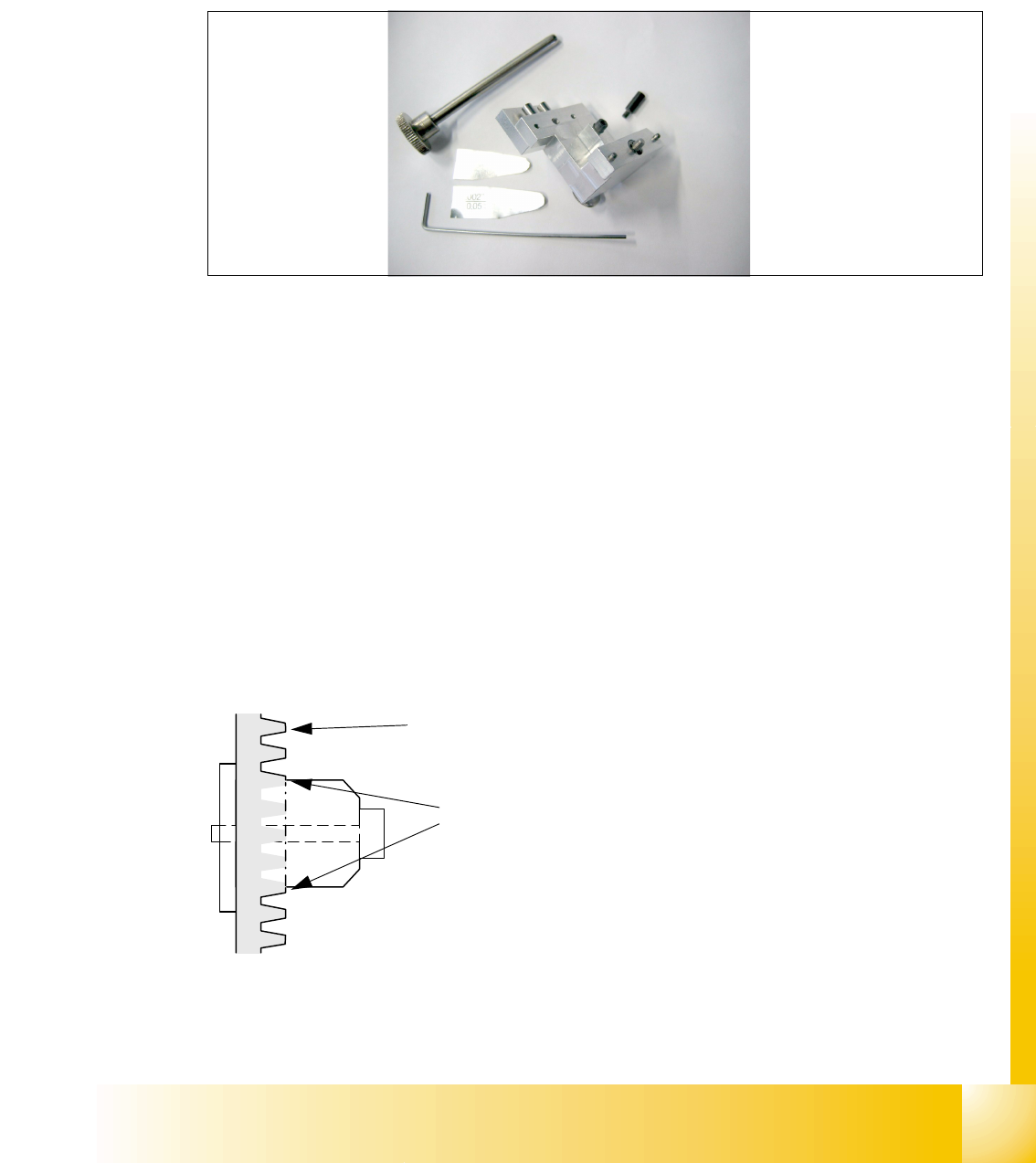
6.4.6.1 Tools and Equipment
– Set of DIN 911 Allen keys
– Gauge for Z-limit stop, item no.03019865-01
Fig. 6.4 - 7 Gauge for Z-limit stop
6.4.6.2 General
With the softwareversion 503.02 and higher the calculation of the zero point correction of the
Z-axis is done with the star in a position of 2700 digits. During the reference run the Z axis (star
axis position +2700 digits) now moves down and up into the aperture. To ensure that the Z axis is
located correctly in the center of the raceway/aperture, it must be possible for the Z axis to move
into the aperture up to the limit stop. This is only possible if the Z limit stop is set correctly.
Preconditions: 6
Before you start with the setting please check the followings:
– Belt tension Z-Axis
– Correctly mounted clamping device on the Z-axis belt.
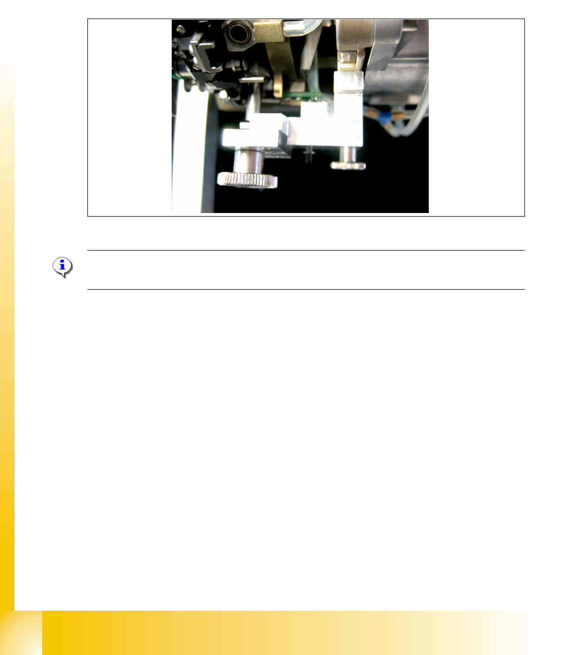
Fig. 6.4 - 8 Clamping device Z-axis
You ensure, so that the clamping device is firmly fixed between the teeth of the drive belt.
Tooth on the drivebelt
Clamping device between the
teeth of the drive belt
1 - 62
Student Guide SIPLACE X
6 Collect &Place-Head 6/12 Edition 09/2005
62
6.4.6.3 Settings
➠ Switch off the machine. The setting can, however, be made directly on the machine.
➠ The star gauge for setting the Z limit stop is mounted on the C&P head in exactly the same way
as the zero point gauge for the star.
➠ Remove the segment 1 from the star and turn the star, so that the gauge pin is inserted on
segment 1.
Fig. 6.4 - 9 Z-Limit stop gauge mounted
Please Note:
For DLM 1 heads an additional adapter must be mounted for the gauge.
– The star gauge ensures that the star is at the correct position and the Z axis is pushed up-
wards.
➠ To obtain better access to the Z limit stop, you should unscrew the cable clip on one side and
twist it away. Push the ribbon cable carefully aside.
➠ Use the 5/100 mm feeler gauge to check that it can be moved freely (without resistance) bet-
ween the Z limit stop and the clamp. (Fig. 6.4 - 10)
If this is not the case, the limit stop must be adjusted.
1 - 63
Student Guide SIPLACE X
Edition 09/2005 6 Collect &Place-Head 6/12
63
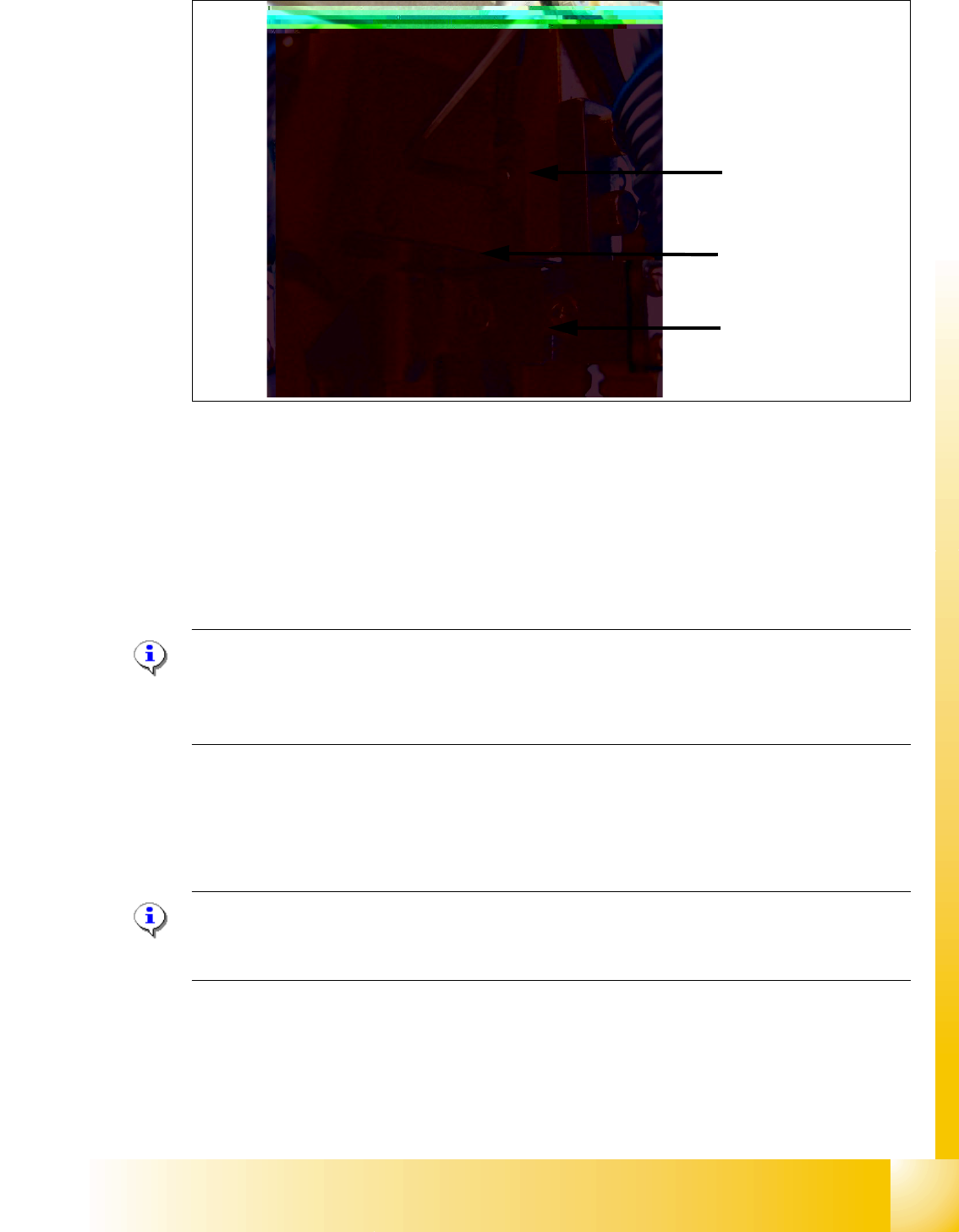
Fig. 6.4 - 10 Z-Limit stop check and adjust
➠ Loosen the screw of the Z limit stop.( Fig. 6.4 - 10)
➠ Clamp a 15/100 mm feeler gauge between the Z limit stop and the clamp. Push the Z limit stop
down gently with a screwdriver and tighten the screw again.
➠ The 15/100 mm feeler gauge should now be difficult to withdraw.
➠ Use the 5/100 mm feeler gauge to check again that it can be moved freely (without resistance).
If this is not the case, the adjustment must be repeated.
Please Note:
When removing the gauge, make sure that the gauge pin is first withdrawn and then the star
gauge is removed. If this is not done, the gauge can wedge between the segments and can pos-
sibly damage the segments!
. 6
6.4.7 Light Barrier, Bottom Position
Plesae Note:
In order to adjust the light barrier, use a parallel pin and adjust it to a distance of 1.0 mm to the
sleeve.
Z-Limit stop
Feeler gauge
Clamping device