SiplaceX4_en.pdf - 第266页
1 - 38 S tudent Guide SIPLACE X 6 Collect &Place-He ad 6/12 Edition 09/2005 38 6.3.22 Det ailed turn ing process at DP -station - Positioning to pick up angle Fig. 6.3 - 19 Detailed turning process at DP-station - Po…
1 - 37
Student Guide SIPLACE X
Edition 09/2005 6 Collect &Place-Head 6/12
37
6.3.20 PCB placement finished
– All components are placed at the corrected placement positions at the PCB board positions.
– After placing the last component the gantry axes move to the waiting position.
– The machine activates the transport system and moves the board to the output conveyor.
– Finally the machine sends the number of consumed components (placed and rejected ones)
to the line computer.
– The OIS (Operator Information System) calculates the placement statistics referring to the pro-
grammed station setup, the programmed cluster or the last reset time. This meaningful place-
ment statistics help to optimize the production process.
– The machine is ready for the next board.
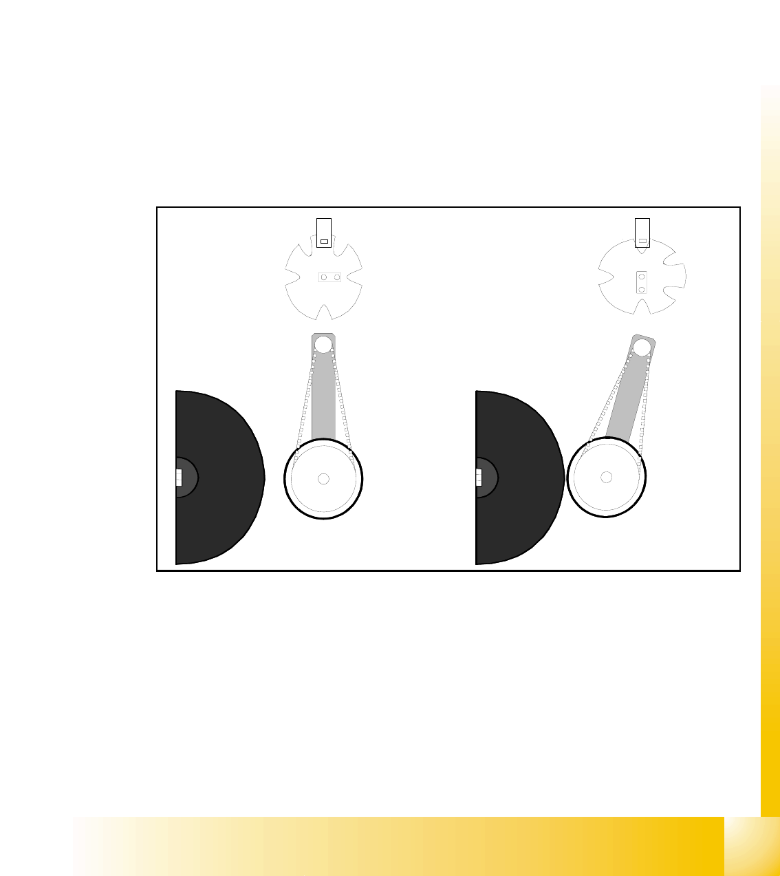
6.3.21 Detailed turning process at DP-station - 1. Swiveling in
Fig. 6.3 - 18 Detailed turning process at DP-station 1. Swiveling in
– Picture 1 shows the initial position.
– From initial position the stepper-motor turns 90° to swivels in.
– The DP-station swivels in and contacts the sleeve (incremental scale).
– The stepper motor is controlled by the light barrier at the cam disc.
– Picture 2 shows the state when swiveled in.
– This is the start requirement for the drive of the DP-axis.
1.
2.
1 - 38
Student Guide SIPLACE X
6 Collect &Place-Head 6/12 Edition 09/2005
38
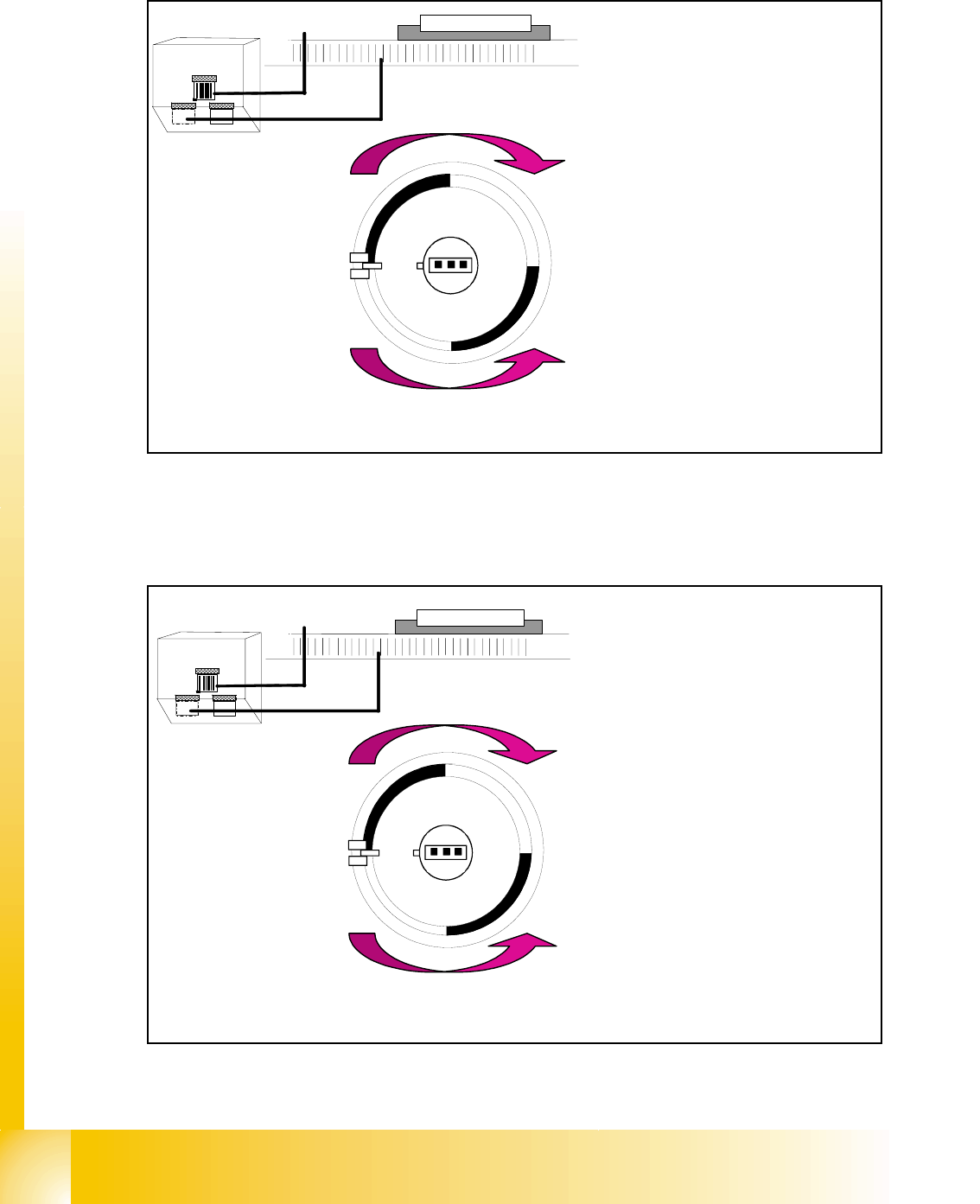
6.3.22 Detailed turning process at DP-station - Positioning to pick up angle
Fig. 6.3 - 19 Detailed turning process at DP-station - Positioning to pick up angle
6.3.23 Detailed turning process at DP-station - Positioning to placement angle
Fig. 6.3 - 20 Detailed turning process at DP-station - Positioning to placement angle
Zero pulse
window
Track signals
bright dark
transition is
zero pulse
¼ turning
Turning directions
– The axis drive moves the seg-
ment to the 0-pulse and checks
the signal level for 3 digits.
– The axis runs in absolute posi-
tioning mode to one of the zero
pulses and check this zero
pulse. For a pick up angle of
90° the axis drive move direct
to the 90° black-bright transi-
tion.
– End signal is set when actual
position deviation is within al-
lowed deviation of position.
– There is no difference between
0° and 180° / 90° or -90° pick
up angle.
Zero pulse
window
Track signals
bright dark
transition is
zero pulse
¼ turning
Turning directions
– When DP-station is swiveled in
the axiscontroller is activated
and ..
– .. the actual position is set to zero
by setting the position counter
DP-axis to 0.
– The DP-drive is operated in rela-
tive positioning mode.
– The DP-axis starts to the target
position taken from calibrated,
programmed and centered val-
ues.
– End signal is set when actual po-
sition deviation is within allowed
deviation of position.
1 - 39
Student Guide SIPLACE X
Edition 09/2005 6 Collect &Place-Head 6/12
39
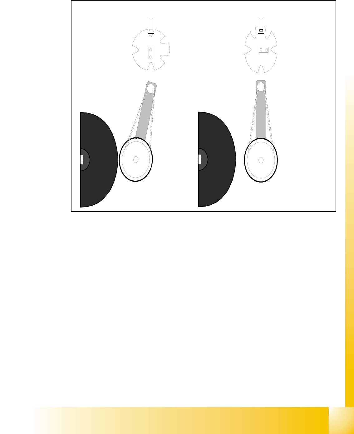
6.3.24 Detailed turning process at DP-station - 3. Swiveling off
Fig. 6.3 - 21 Detailed turning process at DP-station - Swiveling off
– Start requirement for swiveling off is the end signal of DP-positioning.
– The DP-drive contact the sleeve. The positioning is finished with an end signal.
– The stepper motor is controlled by the light barrier on the cam disc.
– Picture 1 shows the swiveled in state.
– From the swiveled in state the stepper motor turn 90° counter clockwise to swivel off.
– Picture 2 shows the swiveled off state.
2.
1.