SiplaceX4_en.pdf - 第175页
1 - 29 S tudent Guide SIPLACE X Edition 09/2005 4 Servic es to the machine 29 Fig. 4.2 - 21 power distribution X 1 q a DC/D C U20 DC/DC U30 com puter unit axi s unit 1 X16 X16 X13 24V 5V se ctor 2 main distri b. X2qa X4q…
1 - 28
Student Guide SIPLACE X
4 Services to the machine Edition 09/2005
28
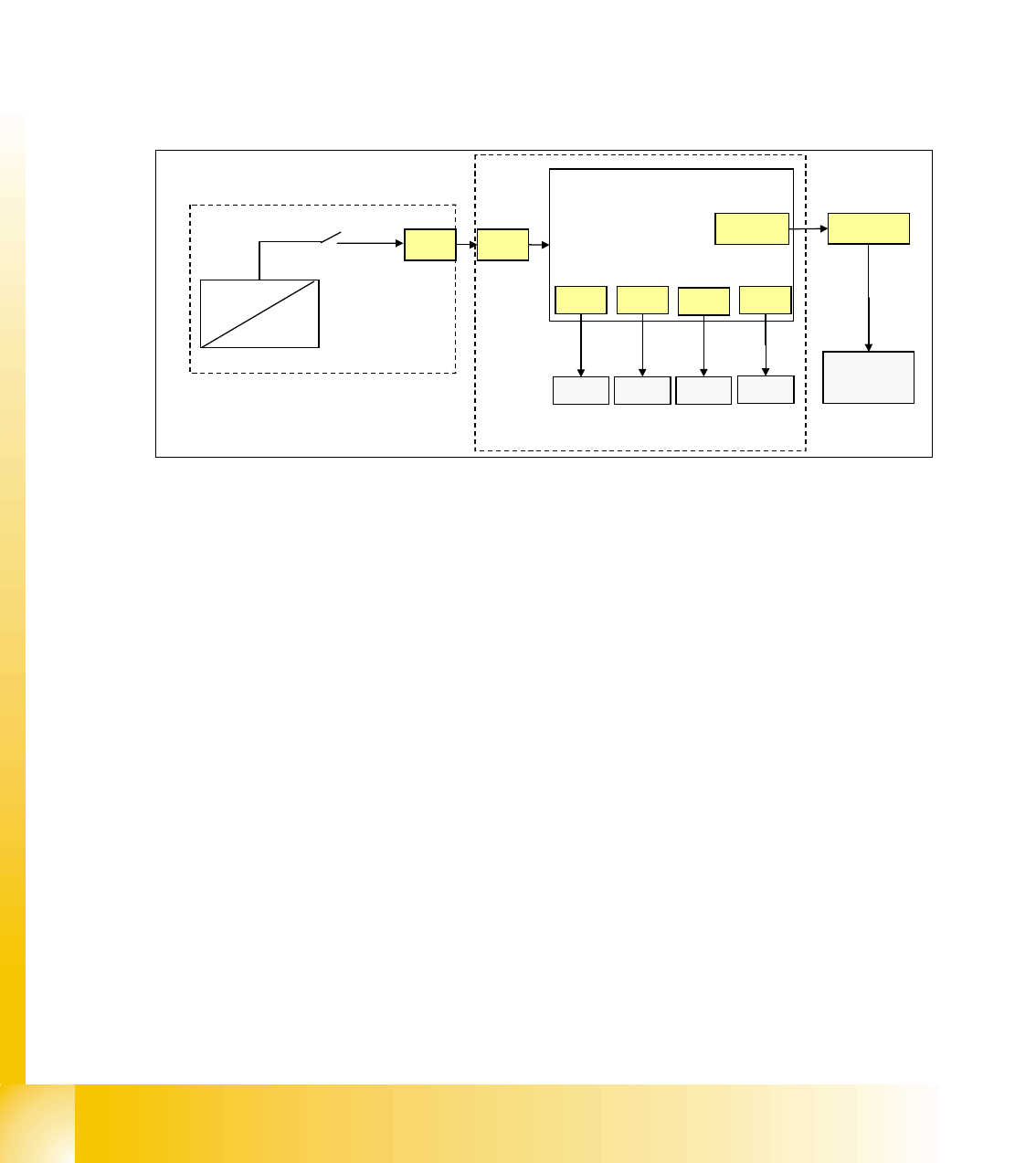
4.2.10.3 Control On signal
With energizing the contactor K4 of power supply, the auxillary contact of K4.5 (K4) get closed.
24 V (servo enable signal) is activated at the DC/DC converter to main power supply distributor
X13 to axis unit X21 and to Anti-Crash board.
Here it is split in 2 paths:
path1: 24 V is activated as the
’servo enable signal’ at anti crash board and at the servo board
X/Y axis (via X31, X32, X33, X34) to enable the servo amplifier (switching GND to the servo board
via optical coupler).
path 2: 24 V is activated as the ’
Ctrl_On’ signal at section 2, connector X4qa and at last at the CAN
I/O module as
M_Ctrl_On. The 4 main axis is allowed to move now into any position.
Fig. 4.2 - 20 Control On signal
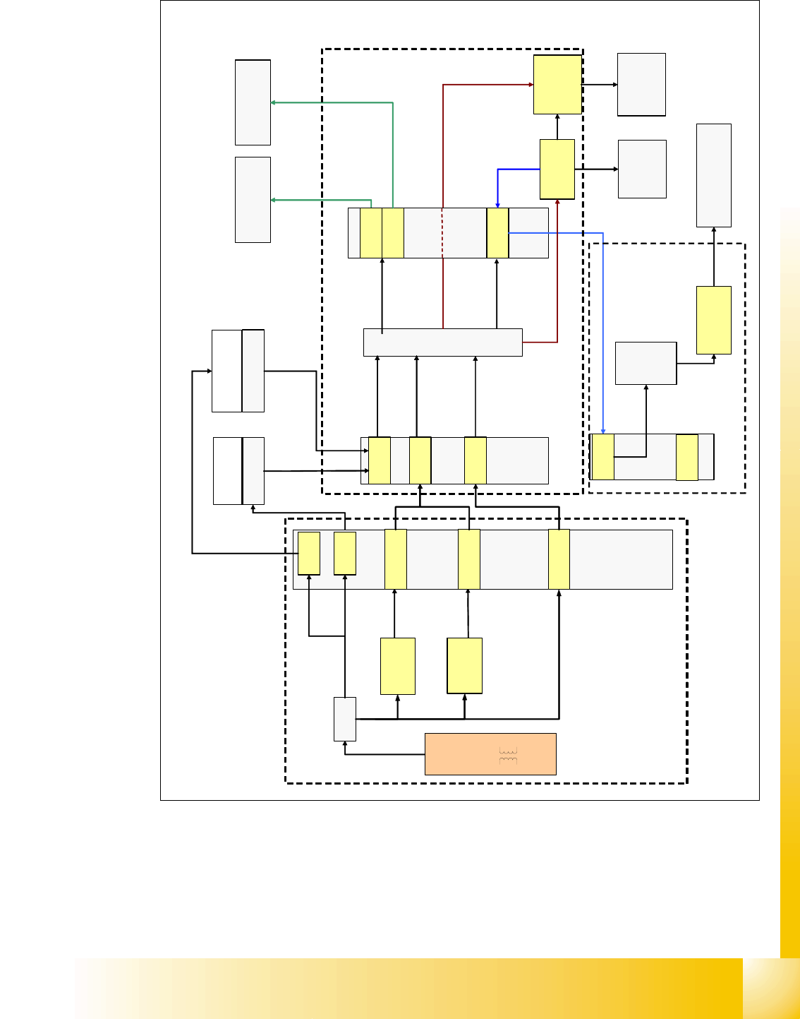
4.2.11 Power Distribution
The power distrubtion to the different section, gantry and heads is highly structured.
5V and 24 V, generated by DC/DC converter U20 and U30 in main power supply, will first activate
at distributor main power supply, connector X16. Then at section 2, main distributor, connector
X2qa and then at the terminal block X1qa for general use, at connector X71qa and at last at
connector X71ra, section 4.
52 V for camera illumination, generated by U7, is activated at main power supply distributor, X18,
and split into two paths.
path 1: at X18, at section 2, X3qa, at terminal strip X1qa and then 52V is activated at the DC/DC
converter vision for converting the 42 V needed for the IC/FC camera illumination. 52V is also
activated at connector X71qa and connector X71ra in section 4, at X1ra and at last at the DC/DC
distributor vision (42V are not used here)
path 2: (this path is presently not shown in overview and not used) 52V is activated at X18 main
power supply distributor, at section 4, X3ra, at terminal strip X1ra and 52V is also activated at the
DC/DC distributor vision for converting the 42 V needed IC/FC camera illumination in this section.
+/-15 V are generated in the power supply axis unit from 52 V and +/-15V is activated at X4qa and
terminal block X1qa to get distributed for general use. +/-15V is activated at connector X74qa and
X74ra in section 4, sub-distributor (not shown in overview ’power distribution’)
X21
X39wo
X4qa
CAN I/O
section 2
axis unit
anti crash
board
power supply
X13
DC/DC
U20
K4.5
24V
servo
X31 X32
X33
X34
servo
servo servo
M_Ctrl_On
servo enable
input
1 - 29
Student Guide SIPLACE X
Edition 09/2005 4 Services to the machine
29
Fig. 4.2 - 21 power distribution
X
1
q
a
DC/DC
U20
DC/DC
U30
computer unit
axis unit 1
X16
X16
X13
24V
5V
sector 2
main
distrib.
X2qa
X4qa
X3qa
U7
+ 52V
T1
X18
section 4 sub distributor
X3ra
(24V, +/-15V, 5V, 3.3V)
(3.3 V not used)
placement
head 1
X5qa
X6qa
placement
head 2
X71qa
X71ra
+
/
-
1
5
V
+
/
-
1
5
V
,
3
,
3
V
5
/
2
4
V
24V +/-15V,
5V, 3,3V
DC/DC
vision
PCB
camera
gantry 2
5
/
2
4
V
5
/
2
4
/
4
2
/
5
2
V
5
2
/
4
2
V
5
/
2
4
/
4
2
V
DC/DC
distributor
X1ra
main
power
supply
distributor
vision
control
unit
+ 52V
5
V
+
/
-
1
5
V
4
2
V
FC/IC-
camera
gantry 2
5
/
2
4
V
5
/
2
4
V
5
2
/
4
2
V
PCB -camera
gantry 1
5
/
2
4
V
5
2
V
5
2
V
+ 52V
(1)
(2)
(3)
(5)
(2)
Legend:
1: main power supply distributor
2: connectors - main distributor section 2
3: sub-distributor section 4
4: terminal block X1qa section 2
5: terminal block X1ra section 4
3
.
3
V
X2
5
/
2
4
/
5
2
V
section 2 main distributor
main power supply
DC/DC
5/+-15V
DC/DC
3.3/5V/+-12V
(4)

1 - 30
Student Guide SIPLACE X
4 Services to the machine Edition 09/2005
30
Note