SiplaceX4_en.pdf - 第186页
1 - 40 S tudent Guide SIPLACE X 4 Services to the machine Edition 09/2005 40 4.3.3.6 Safety valve X60 Safety valve for controlling the co mpressed air for trans port and tape cutter . Air supply for trans- port and tape …
1 - 39
Student Guide SIPLACE X
Edition 09/2005 4 Services to the machine
39
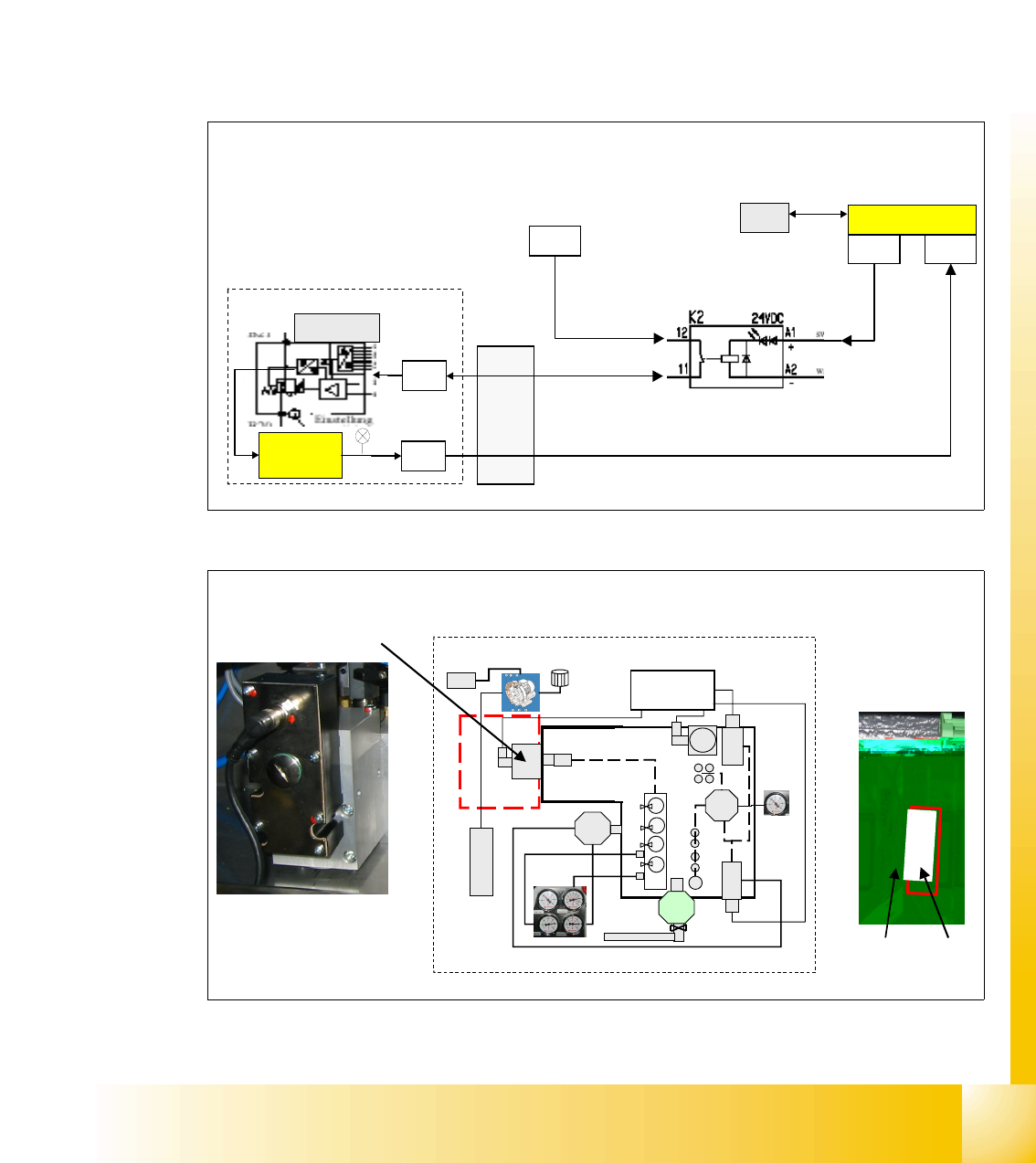
4.3.3.5 Proportional valve, proportional regulator X58
When switching the machine on at the main switch, air is supplied to all placement heads.
After the reference run is performed, the air can be switched of by software after a certain time
(as standard 2 min.) and no air run through the vacuum system of the placement heads.
It automatically regulates the internal machine pressure to 4.8 +0.1 bar for the placement heads.
Included within this regulator block is a pressure sensor which monitors the outgoing air pres-
sure. If the pressure is too low, the A/D converter provides an output of 24 VDC. This signal is
supplied via the CAN I/O module in section 4 (pressure too low) and via the CAN bus to the
machine controller. The valve is controlled by relais K2, located in section 2, main distributor,
relay K1 is not used.
Fig. 4.3 - 8 proportional valve X59 ON/OFF process
Fig. 4.3 - 9 poroportional valve in main pneumatic unit
X7qb X4qb
X21qa
24 V
CAN I/O section 2
o
u
t
p
u
t
v
a
l
v
e
OF
F
GND
power supply 24 V
air ON / OFF
input message pressure 4.5 +O.K
X1qa
MC
prop. valve
pressure
sensor
X58
X58
Main pneumatic unit,
proportional valve
Main pneumatic unit
Section 2, relay K2
Relay
K2
K
2
Relay K1
(not used)
1 - 40
Student Guide SIPLACE X
4 Services to the machine Edition 09/2005
40
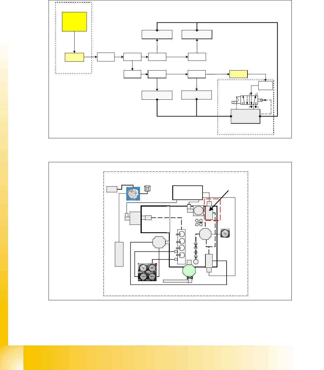
4.3.3.6 Safety valve X60
Safety valve for controlling the compressed air for transport and tape cutter. Air supply for trans-
port and tape cutter is only present, after the start button is pressed and all safety requirements
are fullfilled (safety loop closed).
Fig. 4.3 - 10 safety valve tape cutter
Fig. 4.3 - 11 safety valve location in main pneumatic unit
X2qa
X71qa X22qa
tape cutter 3
X17qa
tape cutter 2
SSK
X16
X71ra X22ra
tape cutter 4
X17ra
tape cutter 1
X21ra
2
4
V
power supply
24 V
5+0.1 bar
tape cutter
safety valve
5+0.1 bar
5+0.1 bar
main pneumatic unit
X60
main pneumatic unit
safety valve
1 - 41
Student Guide SIPLACE X
Edition 09/2005 4 Services to the machine
41
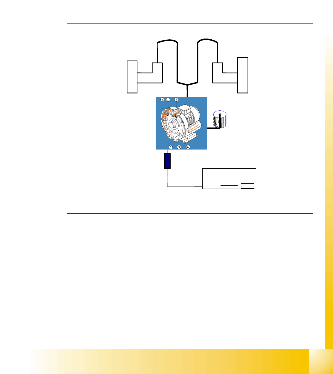
4.3.3.7 Pneumatic loop Cooling Y - Linear motor for Placement area 1/2
For the purpose of cooling the Y-motors an additional pneumatic system is integrated, which suck
the air from the environment, compress it by a compressor and blows it through a hose system to
each of the y-axis motor. The compressed air releases the motor on a lateral point.
The temperature of the Y-axis coils is monitored and when it exeeds 110 C, a message appears
at the monitor. To be very sure, the Y-axis does not get overheatet, is the reason for this simple
cooling system.
Fig. 4.3 - 12 cooling system Y-axis motor
Legend valid for HF:
1. compressor, located in main unit
2. start up unit for compressor
3. Y-axis motor placement area 2
4. Y-axis motor placement area 1
5. air hose for air supply used for cooling the linear motor
Power supply
X3_1
motor for
generating
compressed air
Y-motor BB1
Y-motor BB2
air hose
air hose
motor
"Start up" unit
F14
03003566
Filter
2
3
1
5
4