SiplaceX4_en.pdf - 第125页
1 - 55 S tudent Guide SIPLACE X Edition 09/2005 3 Communication and Control 55 3.5.2.2 Function Control with Caccia Nozzle changer used as example: In addition to the SIT EST program, there are two ot her options for tes…

1 - 54
Student Guide SIPLACE X
3 Communication and Control Edition 09/2005
54
Allocation of subsystems to the hardware components
Example of PA1 on HF/HF3
PPW --> Nozzle Changer (NC)
Subsystem Hardware components Comments
Temperature, 1, coupler, 00 PCB:1 wire trailing interface Trailing interface gantry 1
Temperature, 4, coupler, 00
CB:1 wire trailing interface
Trailing interface gantry 4
PPW, 4, coupler, 00 1 wire hub for NC Hub for NC at location 4 for NC row 1/2
PPW, 1, coupler, 00 1 wire hub for NC Hub for NC at location 1 for NC row 1/2
Mainpath, 0, IO_2C, 01
Mainpath, 0, E2_512B, 01
1 wire RS232 bridge I/O module board (to be later integrated
into I/O module)
Temperature, 1, E2_512B, 81
Temperature, 1, E2_32B, 01
Temperature, 1, E2_512B, 61
Temperature, 1, temperature, 10
Temperature, 1, temperature, 11
Temperature, 1, IO_2C,01
Temperature sensors
gantry 1
The two temperature sensors form a unit
and can only be replaced as a set. The
part for the gantry recognition can not
change.
Temperature, 4, E2_512B, 81
Temperature, 4, E2_32B, 01
Temperature, 4, E2_512B, 61
Temperature, 4, temperature, 10
Temperature, 4, temperature, 11
Temperature, 4, IO_2C,01
Temperature sensors
gantry 4
The two temperature sensors form a unit
and can only be replaced as a set. The
part for the gantry recognition can not
change.
PPW, 4, E2 32B, 81
PPW, 4, AD, 03
PPW, 4, AD, 15
PPW, 4, AD, 16
1 wire hub for NC at location
4
Shows that the 1 wire hub is connected.
PPW, 4, E2_32, 01
PPW, 4, AD, 01
PPW, 4, IO_8C, 01
Control board in NC
gantry 4, in C&P20 NC only
Control board of NC row 1.
PPW, 4, E2_32, 02
PPW, 4, AD, 02
PPW, 4, IO_8C, 02
Control board in NC
gantry 4, in C&P20 NC only
Control board of NC row 2.
PPW, 1, E2_32B, 81
PPW, 1, AD, 03
PPW, 1, AD, 15
PPW, 1, AD, 16
1 wire hub for NC at location1 Shows that the 1 wire hub is connected.
PPW, 1, E2_32B, 01
PPW, 1, AD, 01
PPW, 1, IO_8C, 01
Control board in NC
gantry 1, in C&P20 NC only
Control board of NC row 1.
PPW, 1, E2_32B, 02
PPW, 1, AD, 02
PPW, 1, IO_8C, 02
Control board in NC
gantry 1, in C&P20 NC only
Control board of NC row 2.
1 - 55
Student Guide SIPLACE X
Edition 09/2005 3 Communication and Control
55
3.5.2.2 Function Control with Caccia
Nozzle changer used as example:
In addition to the SITEST program, there are two other options for testing the function of the nozzle
changer.
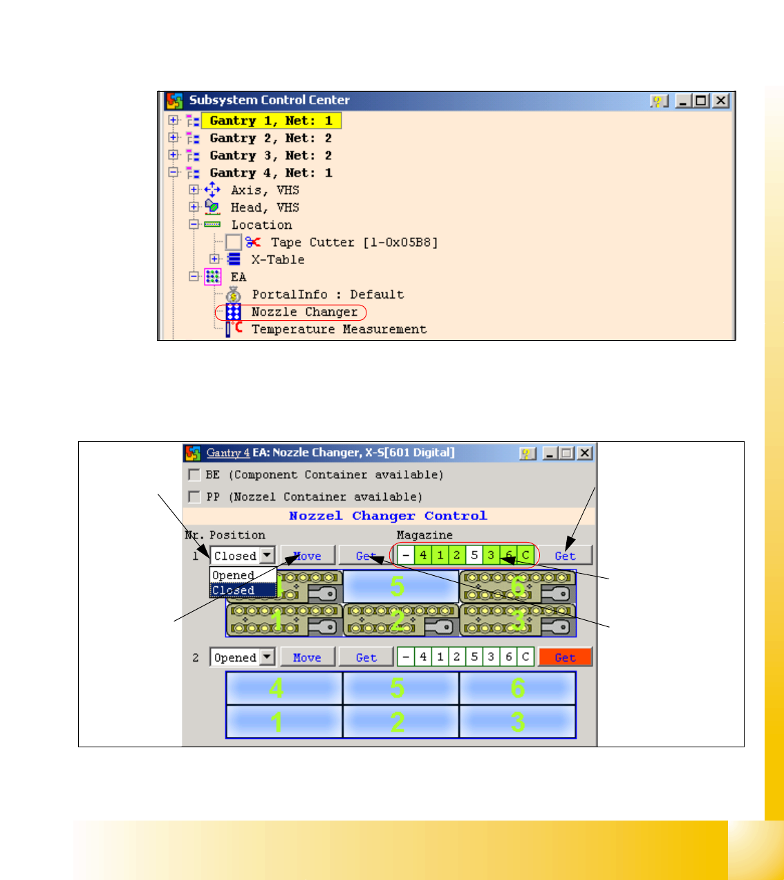
1. NC menu 3
– Open the IO directory of the relevant location in the subsystem control center.
– Doubleclick on Nozzle Changer.
Fig. 3.5 - 15 Subsystem control center (nozzle changer)
– the following menu will appear:
Fig. 3.5 - 16 I/O nozzle changer
Status query maga-
zine (micro switch un-
der the magazine)
Selection win-
dow, open/
close NC row
1
Status display
magazine
Performs the
selected func-
tion
Status display
NC opened / closed
1 - 56
Student Guide SIPLACE X
3 Communication and Control Edition 09/2005
56
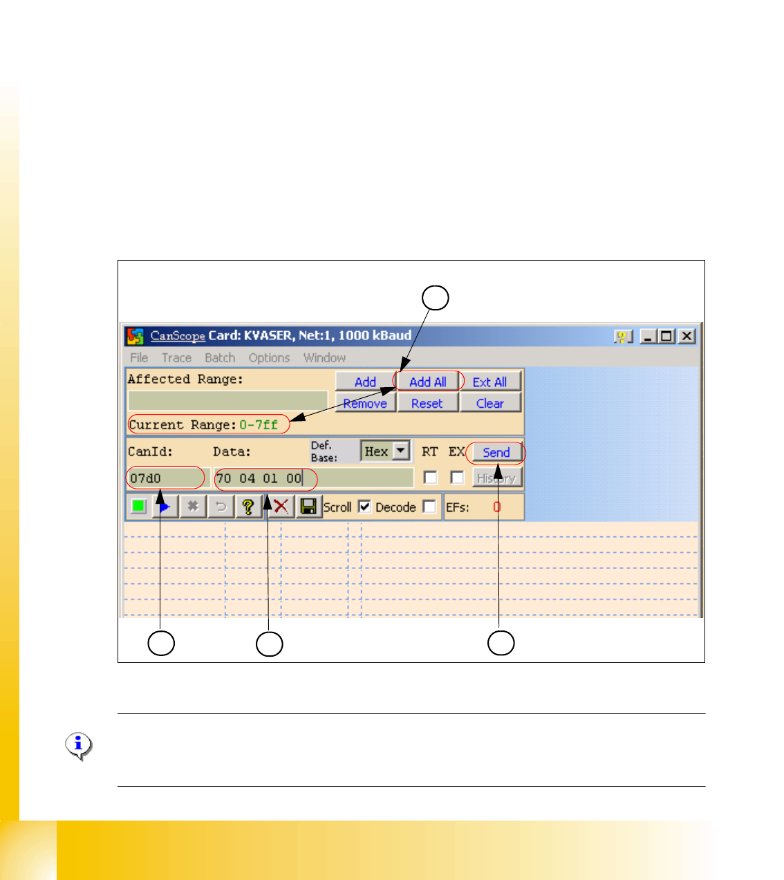
2. Function Control with CAN Bus Commands 3
Open and close the nozzle changer
Preparation: see subsystem queries.
– Open the network window.
– (1) Select the address area "Add All", the current range field will show 0-7ff.
– (2) Enter the CAN ID for the relevant CAN bus path.
Placement area 1 07d0
Placement area 2 07c0
– (3) Enter the command 70 04 01 00 with spaces:
70 --> Move command
04 --> Gantry 4
01 --> NC row 1
00 --> Open (open NC) / 01 --> Close (close NC)
– (4) Click on the "Send" button.
The relevant NC should now open or close, as required.
Fig. 3.5 - 17 Can scope NET 1 1MBaud
Note:
Direct CAN bus commands should only be used by specially trained and qualified service techni-
cans. 3
1
2
4
3