SiplaceX4_en.pdf - 第281页
1 - 53 S tudent Guide SIPLACE X Edition 09/2005 6 Coll ect &Place-Head 6/12 53 6.4 Adjustment s 6.4.1 Description of the PCB bo ards on the 6/12 C&P head All described adjustment s in this chapter are he ad spezi…
1 - 52
Student Guide SIPLACE X
6 Collect &Place-Head 6/12 Edition 09/2005
52
6.3.37 Description air kiss control
Air kiss control at placement: 6
Value “0” mean the blast air valve don‘t switch on.
(1) Value “1-50” mean blast air valve is switched OFF when stepper motor valve drive start to
move.
(2) Value “51-150” mean blast air valve is switched OFF when stepper motor valve drive moved
for 90 degree.
(3) Value. “151-255 mean blast air valve is switched OFF when stepper motor valve drive moved
for 180 degree.
Or at light barrier top.
No value “----” (from converting 501/502 to 503 format) mean same mode than
(3) (existing
standard).
Air kiss control at return component! (not reject) 6
(4) Value and description like (1)
(5) Value and description like (2)
(6) Value. “151-255” mean blast air valve is switched OFF when stepper motor valve drive moved
for 180 degree.
Please Note
More Information about the air kiss control see chapter C&P head with (Flow chart).
Notes:
1 - 53
Student Guide SIPLACE X
Edition 09/2005 6 Collect &Place-Head 6/12
53
6.4 Adjustments
6.4.1 Description of the PCB boards on the 6/12 C&P head
All described adjustments in this chapter are head spezific and are necessary here for the
6/12 C&P head.
6.4.1.1 Headadapter for 6/12 C&P head
At the head modularity we can use the same head adapter for the 6 and 12 segment C&P heads.
The head adapter must be exchanged if you mounting the Twin head or the C&P 20 head.
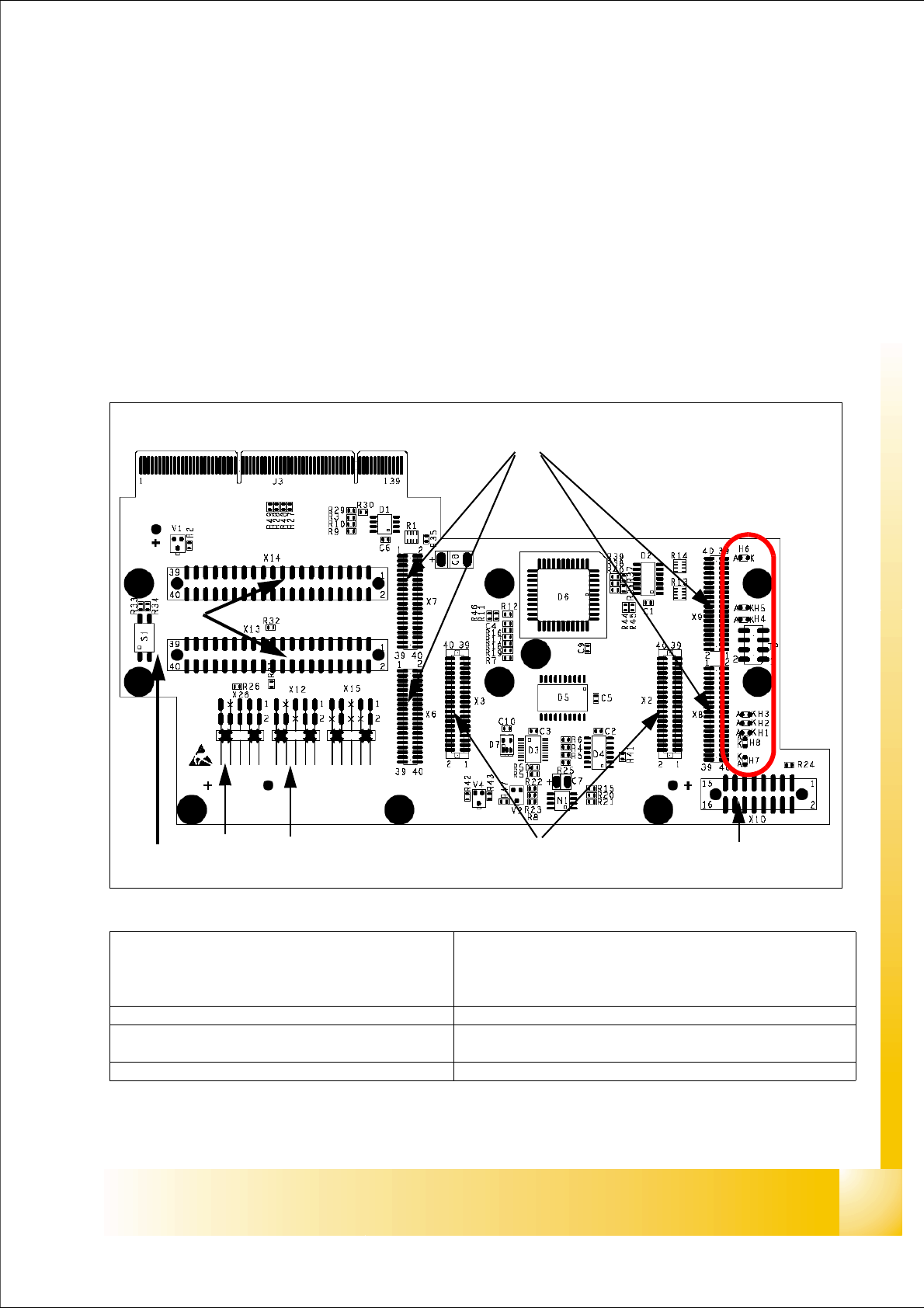
Fig. 6.4 - 1 Headadapter for 6/12 C&P head(03019066-0x)
1
2
45
3
6
7
LED‘S
8
(1)X6 -X9 Connector for CAN Prozessor-board’
80C515C 8Bit not mounted, because these
function make the 16 Bit processor on the head
interface C500.
(2)X2/X3 Connector for the stepping motor board
(3)X10 Connector vacuum board (4) X12 Dp station (motor, track signale)
(5)X26 Option component sensor (6)X13/14 connector for the flat cable to the intermedi-
ate distribution boardr
(7)Connector to the headinterface C500 (8)Switch S1 (see next page)
1 - 54
Student Guide SIPLACE X
6 Collect &Place-Head 6/12 Edition 09/2005
54
Switch S1on the Headadapter board for C&P 6/12 6
When you use the Headadapter with an 8 bit processor on it, so the switch S1 is without function,
because an 8time switch on the 8bit prozessor board is setting this function.
The switch S1 is only activ together with the 16 bit processor which is installed on the head inter-
face.
Switch S1.1:
ON – Testmode (einstellen von CAN ID in BIOS)
OFF – standard setting
Switch S1.2:
ON – Testmode (without delay)
OFF – standard setting (with delay of 3,6ms+/- 300µs)
that means, the Z-Axis move downwards and the light barrier top will be free, after the delay time
of 3,6ms we activate the light barrier bottom.
Description LED‘s on the head adapter: 6
– H6 -LZOS Light barrier Z-axis upper stop
– H5 -LZUS Light barrier Z-axis down position
– H4 -LSM Stepper motor board not connected
– H3 -LSZD Light barrier Swivel in for turning at DP-station
– H2 -LSVZ Light barrier Vacuum / air kiss Z-axis
– H1 -LSVA Light barrier Vacuum / air kiss reject position
– H8 -P15_F 15V Power supply
– H7 -C167
6.4.1.2 Stepping motor board
The stepping motor board for the valve drivers and the swivel function on the DP station is moun-
ted onto the head adapter. Now, the functions are controlled via the 16 Bit processor board on the
head interface.
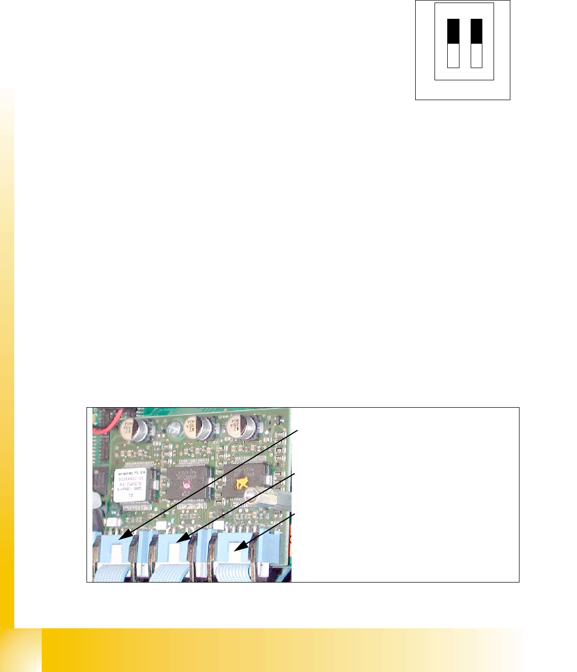
Fig. 6.4 - 2 Stepping motor board
OFF
12
Test
CAN-S
2
3
1
Stepping motor rejectposition
(for X3/X2. X4 and HF-machine)
Stepping motor pick up-, placement-
(and reject position HF/HF3)
Stepping motor DP-axis