SiplaceX4_en.pdf - 第67页
1 - 43 S tudent Guide SIPLACE X Edition 09/2005 2 Overview 43 2.2.12.3 Nozzle Changer for C&P20 Head As an option on placement head s, a nozzle changer can be inst alled for each collect&place head. This enables …
1 - 42
Student Guide SIPLACE X
2 Overview Edition 09/2005
42
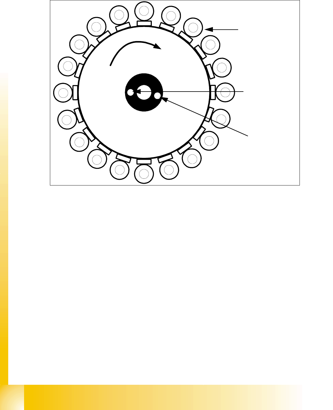
2.2.12.2 Overview of Functions for Star Stations 1 - 20
Fig. 2.2 - 27 Overview of functions for star stations 1 - 20
Star station 1: 2
– Pickup, placement or rejection of component
– Component sensor: checks whether component is present after pickup and before place-
ment.
– Component sensor: checks that there is no component present after placement and be-
fore pickup.
– Measurement of vacuum and air kiss in pickup/placement circuit
Star station 12: 2
– Measurement of vacuum in hold circuit
The star axis can be rotated to enable the vacuum to be measured at each segment.
Star station
11: 2
– Optical measurement of components
Star stations 2 - 10 and 12 - 20 2
The components in the segments of these star stations can be rotated into the correct position.
In star stations 2 - 10 the component is rotated into the placement position.
In star stations 12-20 angle correction is performed after optical measurement.
Rotation into the correct pickup position can be performed at all star stations except 1 and 11.
20
1
3
2
4
5
18
19
6
14
13
12
11
17
16
15
7
8
9
1
0
Star stations 1-20
Measurement of hold circuit
Measurement of pickup/place-
ment circuit
1 - 43
Student Guide SIPLACE X
Edition 09/2005 2 Overview
43
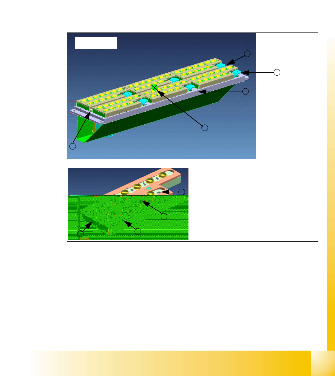
2.2.12.3 Nozzle Changer for C&P20 Head
As an option on placement heads, a nozzle changer can be installed for each collect&place head.
This enables the nozzle configuration to be changed rapidly, thus allowing the collect&place head
to be quickly adapted to the needs of the placement process.
The nozzle changer consists of at least one, and up to twelve magazines, each with twelve nozzle
garages (see Fig. 2.2 - 28). These magazines are mounted on a common support and each mag-
azine is fixed with a pushbutton (release via lever).
Optionally, each garage can be configured with a different nozzle type
Fig. 2.2 - 28 Nozzle changer and nozzle magazine for 12-segment C&P head
Key
(1) Calibration fiducial (2) Nozzle garage
(3) Release (unlocking) lever (4) Magazine carrier
(5) Magazine (6) Green LED (magazine monitoring)
Nozzlechanger C&P Head
4
1
1
1
1
2
3
5
6

1 - 44
Student Guide SIPLACE X
2 Overview Edition 09/2005
44
2.2.13 Conveyor system
2.2.13.1 General
The standard Siplace X machine is supplied with a single conveyor. The dual conveyor system is
available as an option. Depending on your requirements you can choose the left or right conveyor
side as a fixed conveyor side.
In the processing area, the PCB board is clamped from the bottom side against the fixed holder
on the conveyor system. The distance between the top of the PCB board and the C&P Head there-
fore remains the same for each PCB board, regardless of the PCB thickness. This means that the
placement rate is also no longer dependent on the PCB board thickness. Futhermore, fiducial rec-
ognition can be optimized, as the distance between the top of the PCB board and the PCB camera
is always the same. This ensures that the fiducial shape image on the CCD chip of the PCB cam-
era remains in focus.
The 12 C&P head can handle components with a maximum height of 6 mm, the 6 C&P head com-
ponents with a maximum height of 8.5 mm and the C&P20 head components with a maximum
height of 4 mm.
The conveyor system uses a SMEMA or SIEMENS (optional) interface for communication be-
tween the PCB conveyors on different machines and can be adjusted to heights of 830, 900, 930
or 950 mm.
The transfer of PCB boards is monitored and controlled with light barriers which consist of a trans-
mitter module and a receiving module. When the PCB board arrives at the placement area, it is
recognized by a laser beam; the conveyor speed is reduced and the board is clamped into position
from the bottom side.
Clamping 2
The PCB is lifted for the placement process and pressed against the PCB holder (guide rails on
the side). As the lifting table moves upwards, the PCB is lifted and clamped into place with the
complete transportation drive unit. The placement level remains, irrespective of the PCB thick-
ness.
PCBs with lengths up to 450 mm (368mm for the HS60) are clamped in their respective placement
areas and not in the input or output conveyors. However, PCBs with lengths between 450 mm
(368mm for HS60) and 610 mm are placed on the conveyor belt and are only supported by the
lifting table when in the placement area.
Width Adjustment 2
Width adjustment is performed via a motor, after reception of a job from the Siplace Pro computer.
The two conveyor tracks of a dual conveyor can have different widths. The width adjustment step-
ping motor allows PCB widths to be adjusted independently of all other machine components(e.g.
axis gantry). The width adjustment proximity switch on the conveyor side is no longer needed.
The PCB width is adjusted with 3 adjusting units (pneumatic cylinder), installed under the input,
intermediate and output conveyors. These adjusting units are moved synchronously back and
forth by a ballscrew and belt, driven by the stepping motor.