SiplaceX4_en.pdf - 第245页
1 - 17 S tudent Guide SIPLACE X Edition 09/2005 6 Coll ect &Place-Head 6/12 17 6.2.1.1 Initialize V alve Drive at Pick-up / Placement Position / Reject Position The function of the stepper moto r , with the aid of an…
1 - 16
Student Guide SIPLACE X
6 Collect &Place-Head 6/12 Edition 09/2005
16
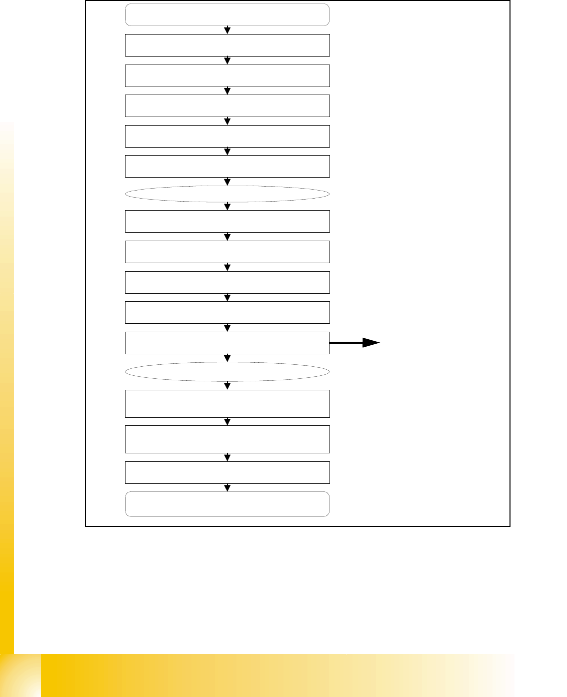
6.2.1 Reference run C&P head
Fig. 6.2 - 1 General reference run C&P head
Press Start Button
Initialise all Stepper motors
Z-Axis pre-reference run
Star-Axis reference run
Z-Axis complete reference run
DP-Axis reference run
Head reference completed
XY-Axis, gantryreference run
XY-Axis move C&P Head to reject bin
sleeves to initial position
Vacuum measurement for all segments
Vacuum reference completed
XY-Axis move C&P Head to fixed
transport rail
Nozzle height measurement
for all segments
Transport reference run
XY axis move to waiting position
Nozzle lenght measurement for nozzles
OPTION
Option:Component Sensor
1 - 17
Student Guide SIPLACE X
Edition 09/2005 6 Collect &Place-Head 6/12
17
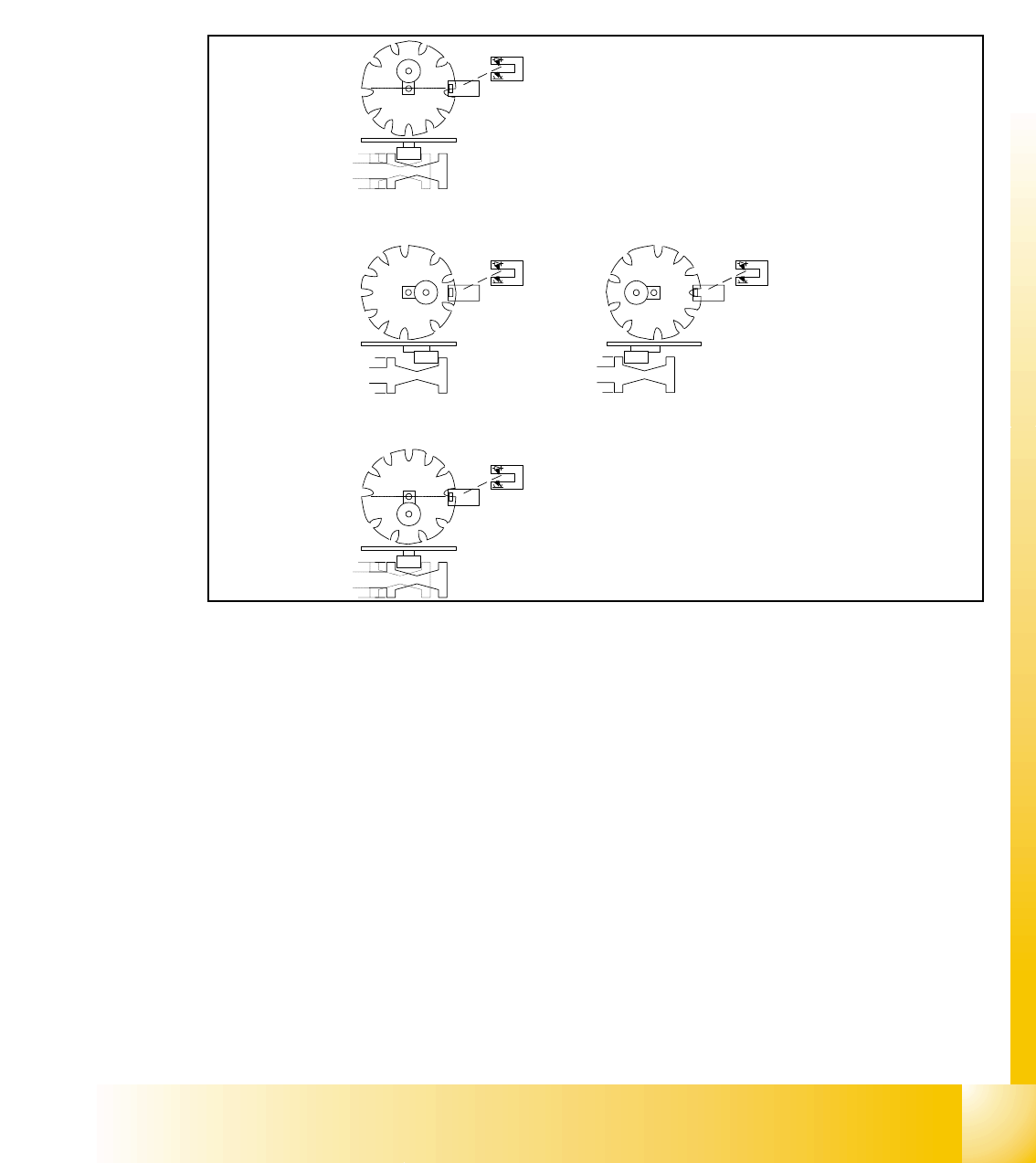
6.2.1.1 Initialize Valve Drive at Pick-up / Placement Position / Reject Position
The function of the stepper motor, with the aid of an eccentric movement, is to move the plunger
which will switch vacuum on and allow component to be picked. When placing the component the
plunger is switch again for nozzle closed, so that we have air kiss on the nozzle for placement.
When reject the component the plunger will switch air kiss on and allow component to be rejected.
After this we switch back on vacuum .
Fig. 6.2 - 2 Initialize valve drive at pick-up / placement / reject position
Key:
1. Home position, initial position. Give way free for Star axis movement. Drawing show 2 possible
positions of the plunger
2. 2a. is switching to vacuum, Vacuum value "Nozzle open"
2b. is switching to air kiss, Vacuum value "Nozzle closed"
3. Counter position to initial position. Give way free for Star axis movement.
– The stepper motor of the valve drive is turned to the home position. The stepper motor runs
and the light barrier on the cam disk sets the end signal.
– Because of the special shape of the cam disk the stepper motor is able to recognize the home
position (1.).
1
2a
2b
3
1 - 18
Student Guide SIPLACE X
6 Collect &Place-Head 6/12 Edition 09/2005
18
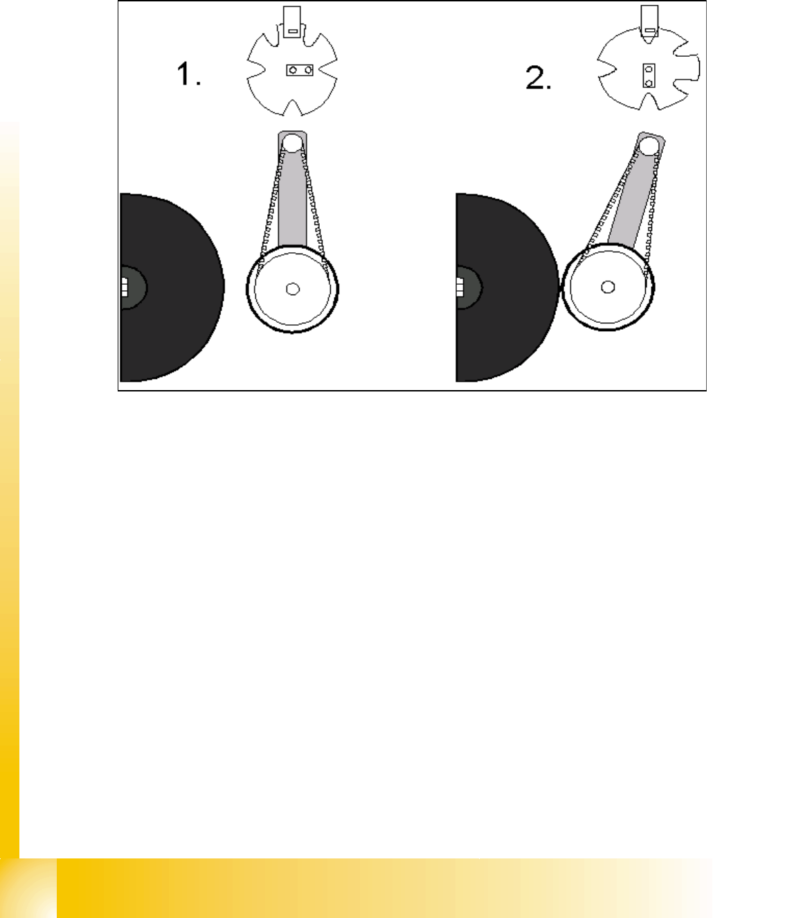
6.2.1.2 Initialize Valve Drive at DP-station
The function of the stepper motor at the DP station, with the aid of an eccentric movement, is to
contact the sleeve and rotate the components and nozzles to the correct position via the DP axis.
Fig. 6.2 - 3 Initialize stepper motor at DP-station
Key
(1) Home position DP drive around 1 mm away from segment
(2) Engaged position DP drive at segment
– The stepper motor of the valve drive is turned to the home position. The stepper motor runs
and the light barrier on the cam disk sets the end signal.
– Because of the special shape of the cam disk the stepper motor is able to recognize the home
position.
(DP german abbrev. for turning sleeve)