SiplaceX4_en.pdf - 第592页
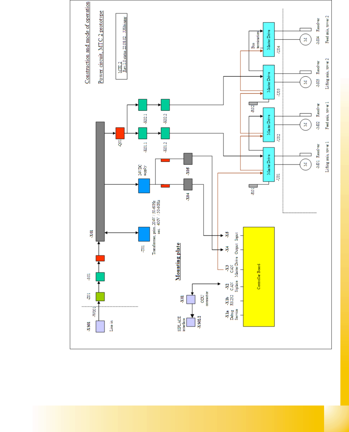
1 - 25 S tudent Guide SIPLACE X Edition 09/2005 13 MTC 2 25 13.2.5 Block diagrams Fig. 13.2 - 4 Power supply block diagram F00 GS01 F01 F02

1 - 24
Student Guide SIPLACE X
13 MTC 2 Edition 09/2005
24
13.2.4.5 Mounting plate
A mounting plate with the following components:
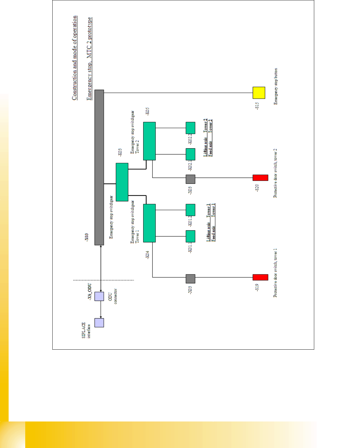
– Combination circuit breakers: K03 - K05
– Braking resistor: R01
– Braking resistor: R02
– Power supply, 24 V DC: T01
– Line filter: Z01
– Discharge reactor (Is this part missing in your MTC please order the retrofitting kit 03016518-
01, that for your own safety.)
Fig. 13.2 - 3 Electronics board and mounting plate
Key
1 Main switches 8 Initiator LED terminals
2 EMERGENCY STOP button 9 Actuator LED terminals
3 Automatic circuit breakers 10 Optocouplers
4 Motor protection switches 11 Combination circuit breakers
5 Contactors 12 Braking resistors
6 Grounding terminals 13 Power supply
7 Through terminals 14 Line filters
15 Discharge reactor
8
3
6