SiplaceX4_en.pdf - 第582页
1 - 15 S tudent Guide SIPLACE X Edition 09/2005 13 MTC 2 15 13.1.6.4 Combination circuit breakers The combination circuit breaker s are fitted on the r ear of the ma sterdrive housing. In the event of malfunctions that a…
1 - 14
Student Guide SIPLACE X
13 MTC 2 Edition 09/2005
14
the relevant safety combination is triggered. The intermediate-circuit voltages (500 V) for the in-
verters are disconnected. Both the lifting and feed axes are deactivated while the logic circuitry of
the inverters continues to be supplied with 24 V DC. The message “EMERGENCY STOP actu-
ated” appears.
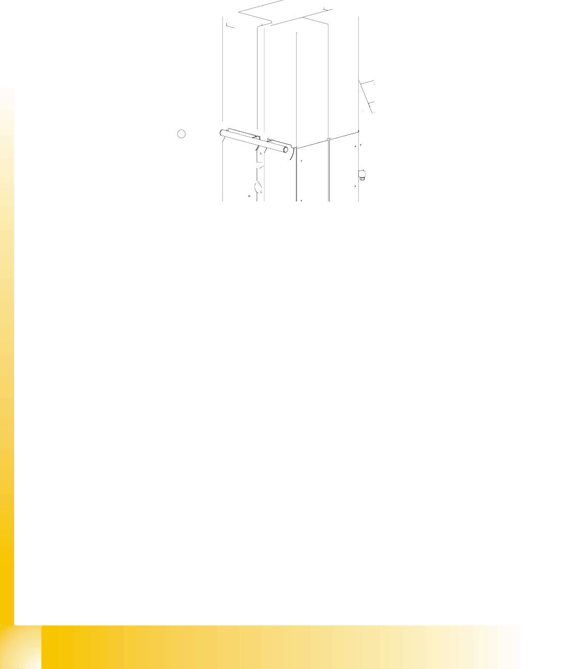
Fig. 13.1 - 19 Location of the EMERGENCY STOP button
Key
1. EMERGENCY STOP button
13.1.6.3 Protective door switches
These switches check whether the two protective doors are closed. If the doors are closed, the
safety contact and the signaling contact are closed. When one of the doors is opened, the safety
circuit and the signaling circuit are opened. The corresponding safety combination is triggered and
the tower is powered down. The following error message appears: “Tower x: Protective cover not
closed”.
Fig. 13.1 - 20 Position of the protective door switches
Key
1. Protective door switches
1
1 - 15
Student Guide SIPLACE X
Edition 09/2005 13 MTC 2
15
13.1.6.4 Combination circuit breakers
The combination circuit breakers are fitted on the rear of the masterdrive housing. In the event of
malfunctions that are relevant to safety, they are triggered.
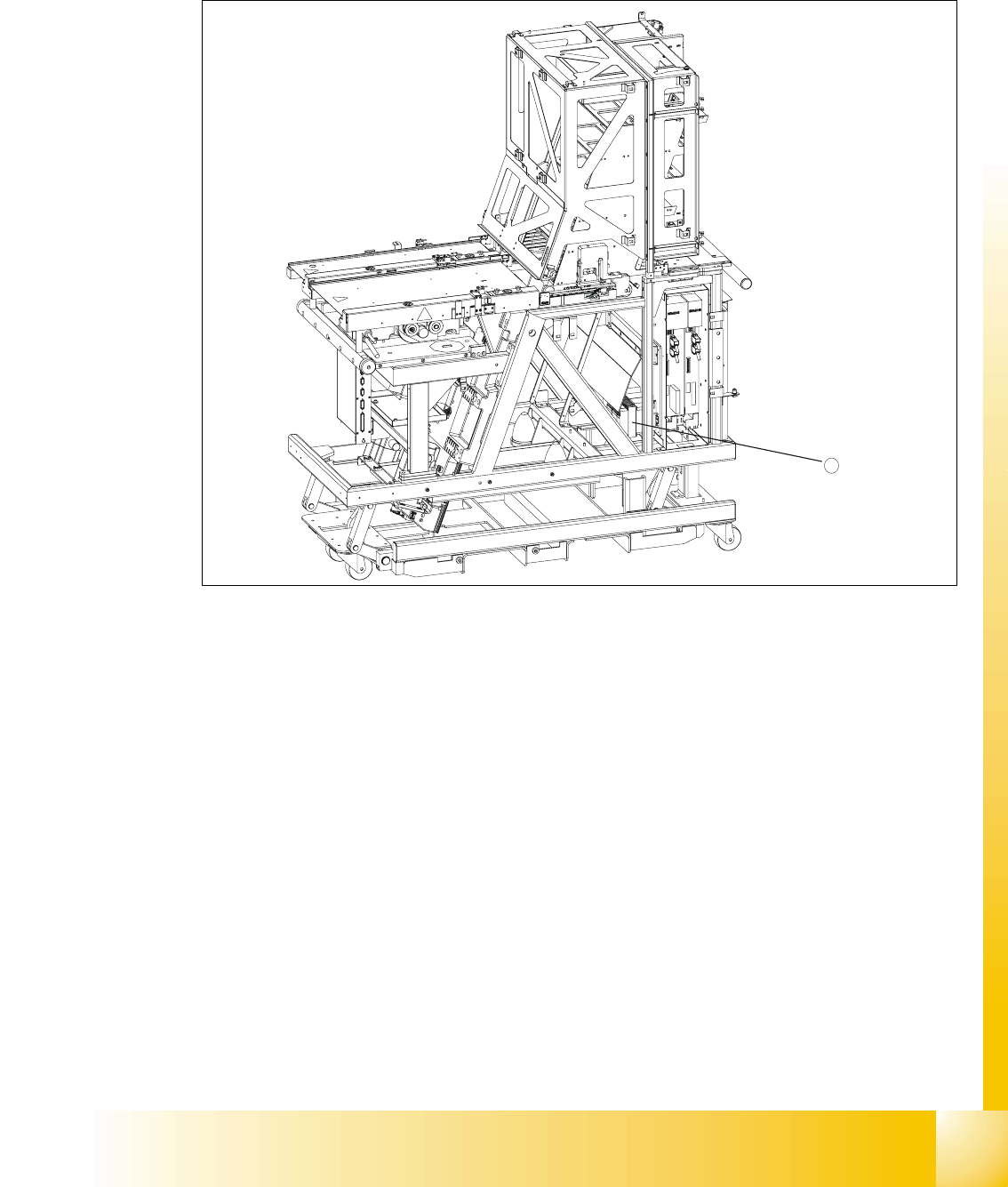
Fig. 13.1 - 21 Position of the combination circuit breakers
1. Combination circuit breakers
13.1.6.5 Safety and signaling circuits
The safety circuit consists of three safety combinations, which work completely independently of
each other. They are used to monitor the following actions:
– Actuation of the EMERGENCY STOP button
– Opening the protective door of tower 1
– Opening the protective door of tower 2
The two protective doors are each equipped with a protective door switch. These are looped
into the starting circuit of the respective monitoring device.
13
If the EMERGENCY STOP button is pressed during operation or one of the two protective doors
opens, the relevant safety combination is tripped and the drives are locked via contactors on the
electronics board.
The signaling circuit for the protective door monitoring system is transmitted to the MTC 2 control-
ler by the relevant safety combinations by means of normally open contacts.
1
1 - 16
Student Guide SIPLACE X
13 MTC 2 Edition 09/2005
16
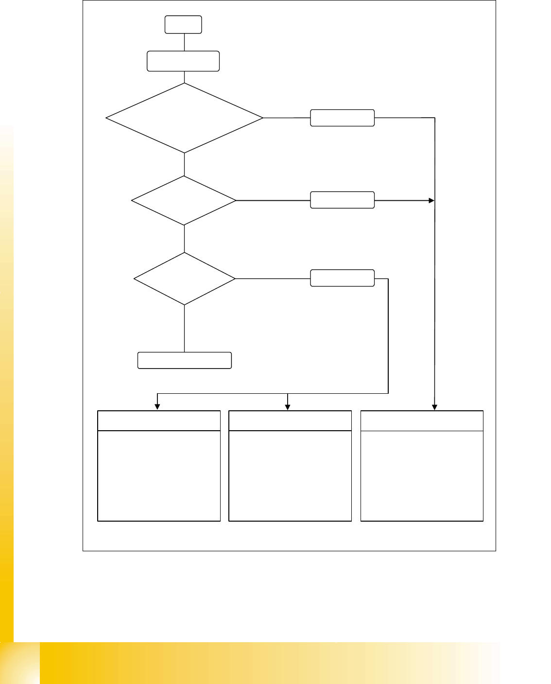
13.1.6.6 Safety loops
Fig. 13.1 - 22 Safety loops
Start
Initialize
Safety loop to
SIPLACE interrupted
Yes
No
No
No
Emergency stop
button pressed
Yes
Yes
Error message
Error message
Protective door
open
Machine inizialized
Tower 1
SSK *) tower 1: not active
SSK *) tower 2: active
Lifting axis 1: 0 V
Feed axis 1: 0 V
Lifting axis 2: 400 V
Feed axis 2: 400 V
Tower 2
SSK *) tower 1: active
SSK *) tower 2: not active
Lifting axis 1: 400 V
Feed axis 1: 400 V
Lifting axis 2: 0 V
Feed axis 2: 0 V
Tower1 andtower2
SSK 1*) tower: not active
SSK 2*) tower: not active
Lifting axis 1: 0 V
Feed axis 1: 0 V
Lifting axis 2: 0 V
Feed axis 2: 0 V
*) CSC Contactor safety combination
Error message