SiplaceX4_en.pdf - 第222页
1 - 28 S tudent Guide SIPLACE X 5 Gantry Edition 09/2005 28 5.5.2 Check dynamic X-axis The inspection of dynamics occurs with the following signals: – Deviation of position – Nominal current – End signal ( Adapte r board…
1 - 27
Student Guide SIPLACE X
Edition 09/2005 5 Gantry
27
5.5 Axis control
5.5.1 Parts for the axis control
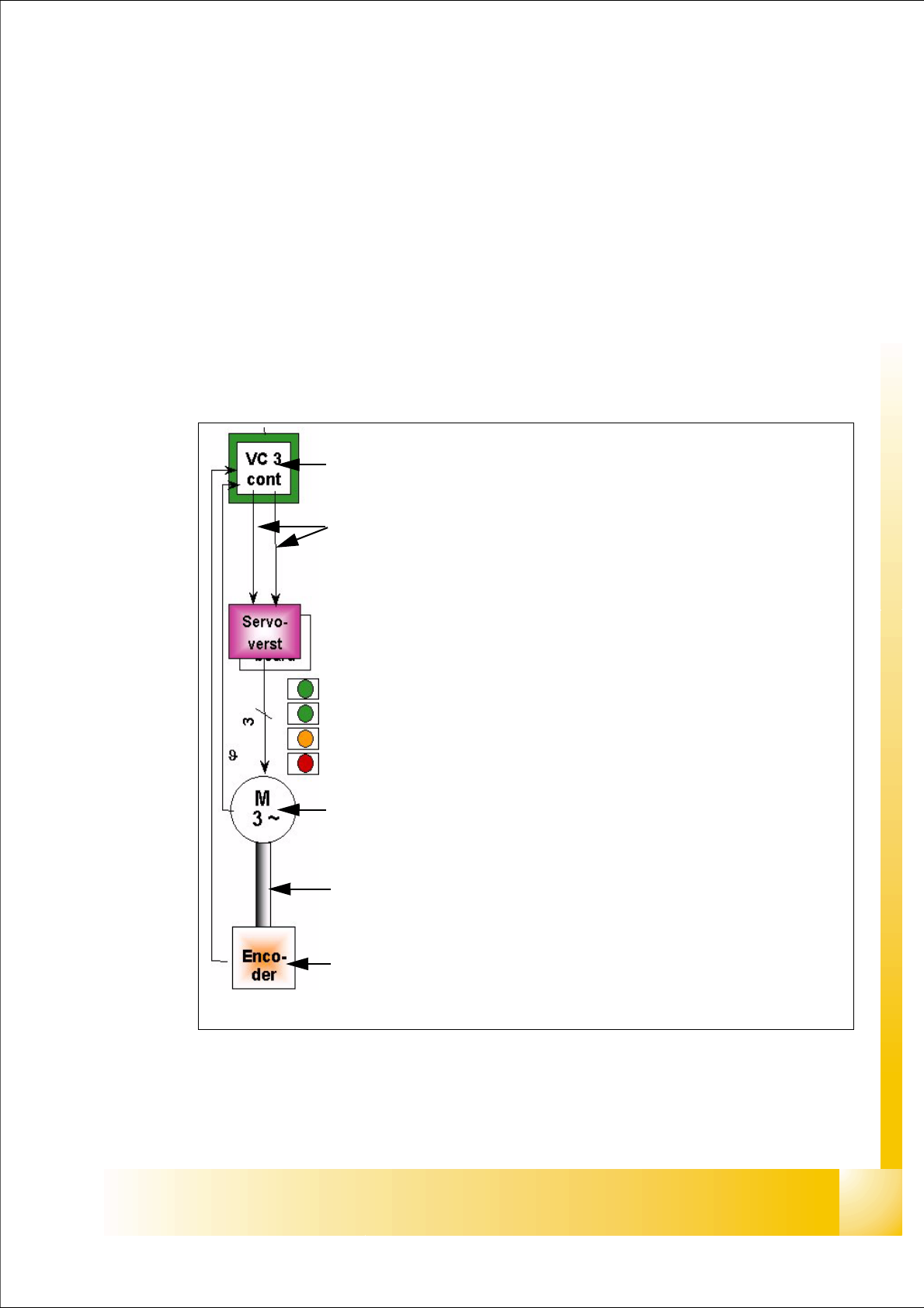
The control loop for control the X- and Y-axis in general consist of the following parts:
– Axis board with VC 3 Controller
– Servo board (TDS)
– 3 Phase AC linear motor
– Measurement system (Incremental scale and encoder)
All linear motors have temperature sensor to protect it against high temperature.
Fig. 5.5 - 1 Parts "Axis control"
Axis board A363 with VC 3 Controller (VC = Velocity Commutation)
Control signals I
soll "W" and I soll "U"
Servo board control directly the linear motor, Intermediate (DC) voltage cir-
cuit is 250V.
LED‘s on Servo board:
– Power supply ON
– Servo enable, it the enable signal from the axis board.
–Display I
RMS limit shorter than 2,5 s.
– Error: Over voltage, -current, -temperature longer than 2,5 sec.
3 Phase AC linear motor X-and Y-axis with integreted temperatur sensor.
Between motor and incremental encoder exist a fixed mechanically connec-
tion.
Incremental encoder: Transmitte the correct position to the axis board and
is the only feedback signal to control the motor (Track signals).
1 - 28
Student Guide SIPLACE X
5 Gantry Edition 09/2005
28
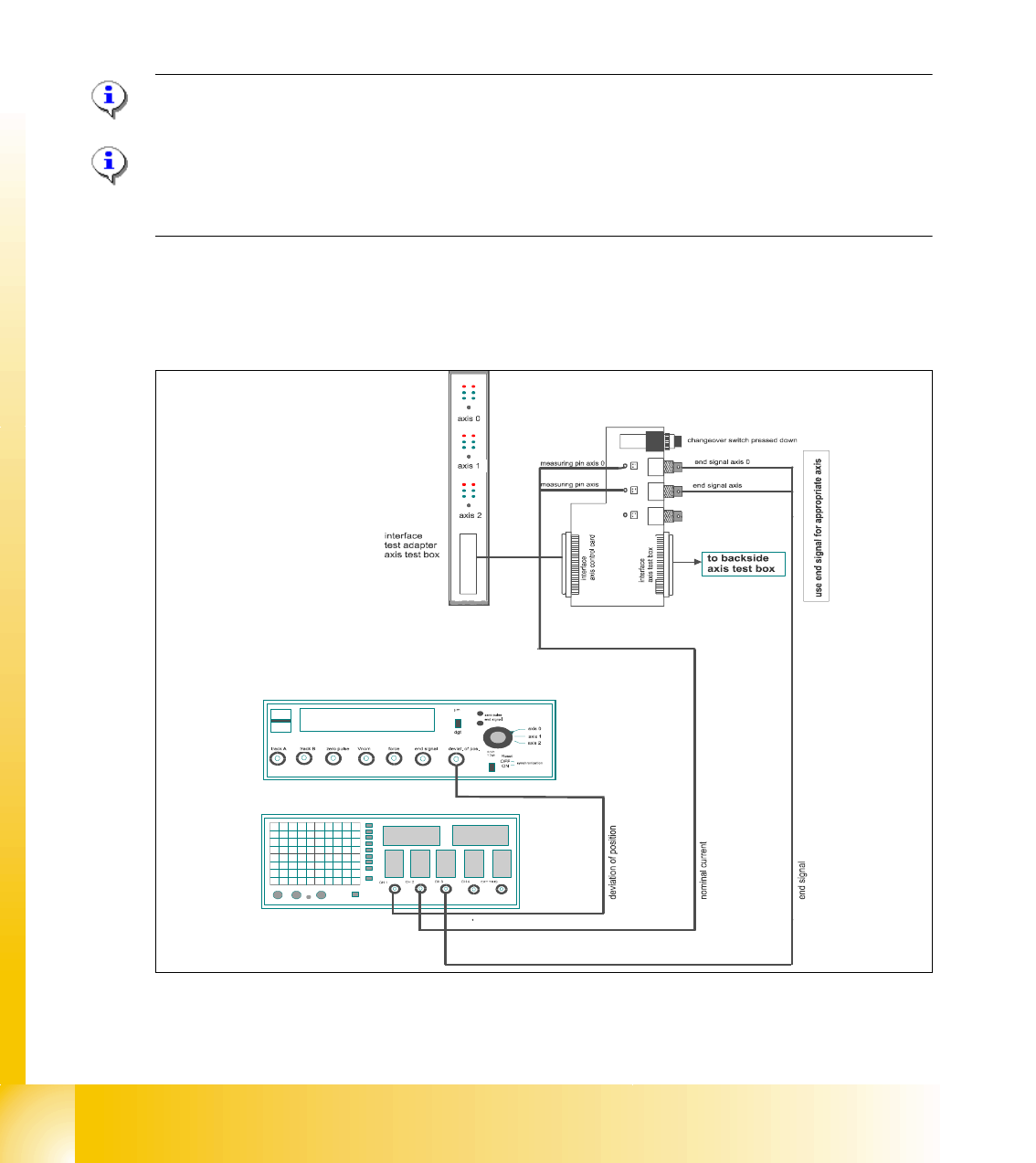
5.5.2 Check dynamic X-axis
The inspection of dynamics occurs with the following signals:
– Deviation of position
– Nominal current
– End signal ( Adapter board Axis in target position)
– Actual position = nominal position ( Axis testbox Output end signal)
Please Note:
For detailed notes to check the axis dynamic, please use the "Adjustment manual".
5
Please Note:
Before adjusting the axes, ensure that the machine has reached its operating temperature.
Switch the machine on at least 30 minutes before you begin work.
5.5.2.1 Test setup with Axis testbox
Fig. 5.5 - 2 Test setup to check the axis dynamic with Axistestbox
– An additional connector on channel 4 is the actual pos.=nom.pos. signal from the axis testbox.
11
1 - 29
Student Guide SIPLACE X
Edition 09/2005 5 Gantry
29
Please Note:
Use an RC - filter to record the unkomutated motor current signal. 5
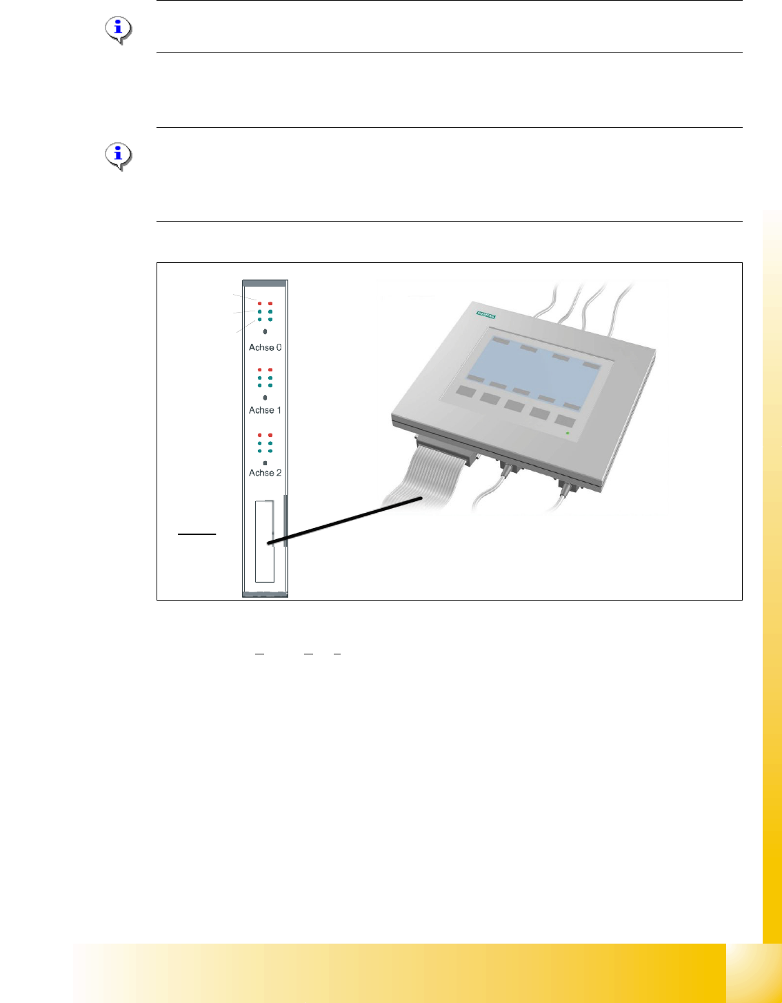
5.5.2.2 Test setup with SAT-Box
Please Note:
-> for dynamic check it may be enough to check positioning time and overshoots of the
axis with the display at SIPLACE Axis Tester and the values from adjustment tables.
-> for troubleshoting the dynamic analysis have to be done with a appropriate oscilloscope5
Fig. 5.5 - 3 Test set up with Siplace AxisTester
Legend outputs Siplace Axis Tester to oscilloscope channels
On account of the higher accuracy requirements at a gantry with Twin head und the higher speed
for C&P 20 head run the X- and Y-axes with different axis control parameters compared with C&P
6 or 12 DLM 2 heads (see followings diagrams).
(1) V
nom
output (motor phase current signal I
W
)
not connected to the scope for HF
(2) uncommutated nominal current (Vreg)
connect to CH2
(3) Deviation of position connect to CH1 (4) End signal connect to CH 3
Axis unit error
Servo ON
Initialize
Counter error
Zero puls
End signal
Interface:
Test adapter,
Axis test box,
SAT-Box
2
4
1
3