SiplaceX4_en.pdf - 第378页
1 - 12 S tudent Guide SIPLACE X 8 Collect&Place-Head 20 Edition 09/2005 12 8.1.3.6 DP-Drive Measurement System with Hall Sensors – Function : The sensor detect s the movement of ferromagneti c ma terial (toothed whee…
1 - 11
Student Guide SIPLACE X
Edition 09/2005 8 Collect&Place-Head 20
11
8.1.3.5 Star
The mechanical collector ring consists of a stationary and a rotary part. The 6 sliding contacts
transmit direct voltage (24V/4A), ground and the CAN bus signals (CAN high, CAN low).This E/D
transmitter (Energy/Data Transmitter) can be replaced during service work.
Star carrier 03005117-0x / collector ring (E/D transmitter) 03007834-0x
2
3
1
4
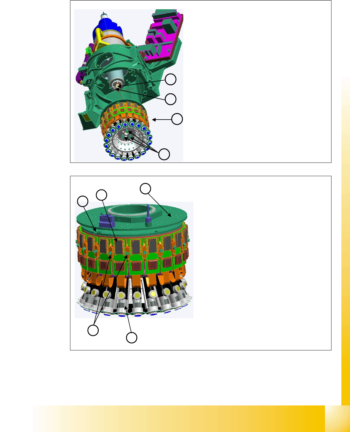
Star axis
The star consists of the star assembly, on which all
20 DP drives are mounted, the motherboard and the
collector ring.
This complete unit is fixed to the motor shaft with
three screws and can be removed for service work
after the raceway has been dismounted.
Star Details
Motor shaft (1)
Star assembly (2)
Screws (3) mounting the star unit to the motor shaft
Smoothed distributor disc
(4)
1
3
2
4
5
Star assembly
The collector ring (1) is located above the star and
supplies the DP drives
(3) with power and data.
The motherboard is located behind the control
boards
(2) of the DP drives and is responsible for
controlling and positioning the DP drives.
The control board is plugged into the mother-
board and is fixed via the two brackets
(4).
Two screws fix the complete DP drive unit from
inside, to the star frame.
An index screw
(5) ensures that the ED trans-
former is correctly positioned during assembly.
1 - 12
Student Guide SIPLACE X
8 Collect&Place-Head 20 Edition 09/2005
12
8.1.3.6 DP-Drive
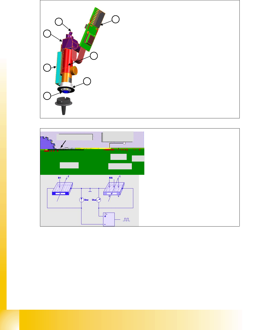
Measurement System with Hall Sensors – Function:
The sensor detects the movement of ferromagnetic material (toothed wheel) through changes to
the magnetic flow.
If one element is opposite a ferromagnetic tooth and another opposite a gap, this causes a one-
sided increase in induction.
The difference arising between the two elements alters the polarity once the toothed wheel moves.
This change is evaluated, digitized and used to address or give feedback in closed-loop control.
The skilled arramgement of the position encoder make one solely Zero position on the DP-Drive.
1
3
2
4
5
7
6
DP Axis
– The DP axis is responsible for turning the compo-
nent into the correct placement position within a set
time. The hollow designed shaft of the DP axis pro-
vides vacuum and air kiss to the nozzle.
– The complete DP drive can be replaced during work.
DP Drive Details
– Control board (1) for DP motor
– Motor
(2)
– Linear guide (3) Z-axis
– Vacuum connection
(4)
– Position encoder system
(5) with resolution of 72 digits/°
– Collar (trigger ring for light barrier bottom)
(6)
– Filter disc
(7)
gear
Power
supply
Hall sensor
0V GND
Output
Load
DP Drive - Function
The DP drives are controlled by the DP
master, in accordance with the counter
pulse and set value (pickup angle, place-
ment angle and correction angle after Vi-
sion).
The DC motor is monitored by a measure-
ment system attached to the motor axis.
1 - 13
Student Guide SIPLACE X
Edition 09/2005 8 Collect&Place-Head 20
13
8.1.3.7 Star Drive
5
4
6
6
1
1
2
2
3
3
5
5
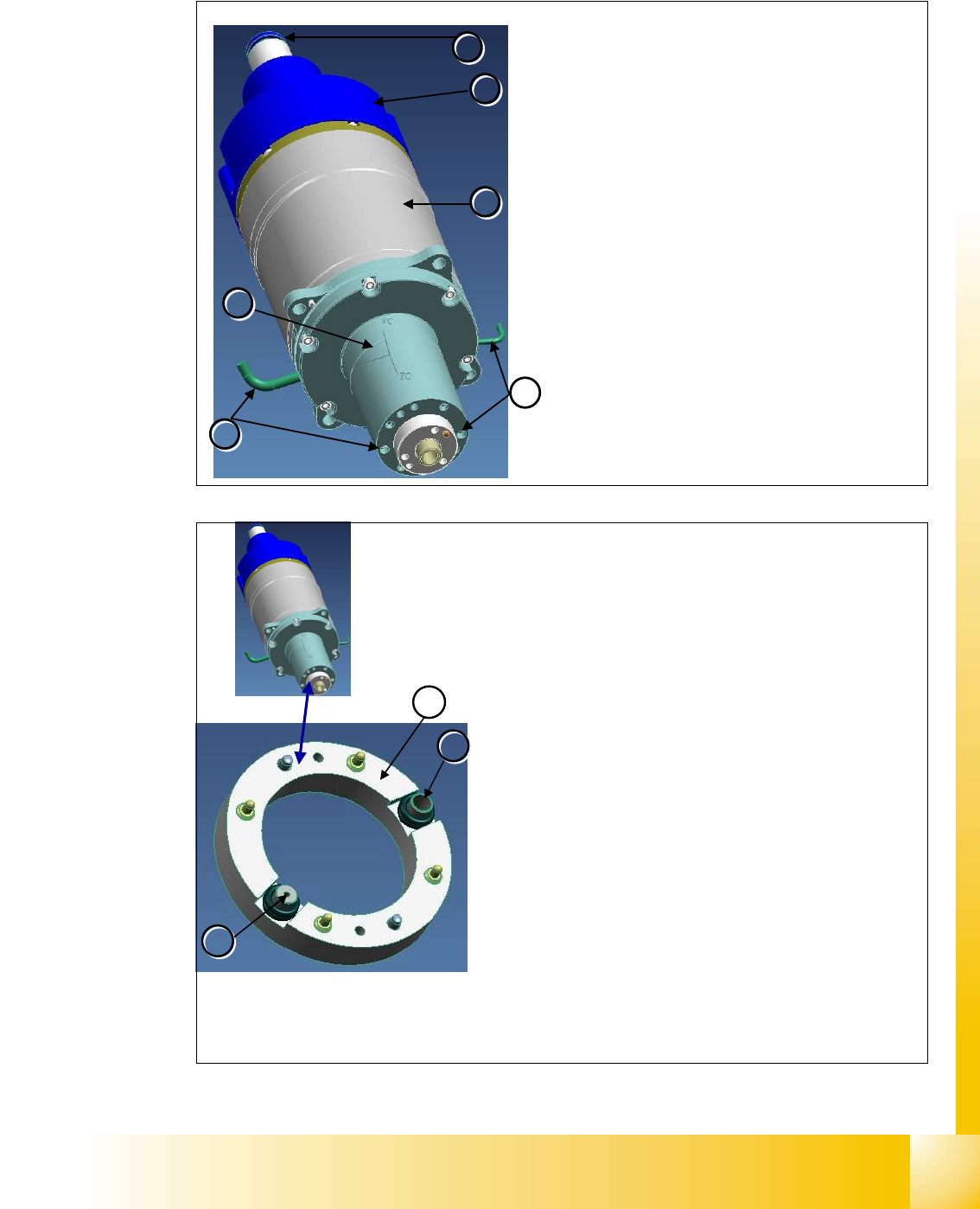
Star Motor
The star motor has a brushless three-phase drive
with integrated measurement system.
The motor shaft has a hollow design. This enables
compressed air to be supplied to the holding circuit of
the 20 segments.
Vacuum in the holding circuit is measured via the con-
nection
(4).
Air kiss and vacuum in the pickup/placement circuit is
measured via the connection
(5).
The star motor is not a spare part.
Star Motor Details
– 3-phase drive (1)
– Incremental measurement system (2)
– Compressed air connection for hold circuit (3)
– Flange on the motor shaft (6).
1
2
2
3
3
– The star motor is a brushless three-phase drive with si-
nus commutation.
– An optical measurement system is used for both commu-
tation and recognition of the rotary angle.This supplies
the track signals A, B and the zero pulse.
– The motor is controlled with the help of these track sig-
nals. The actual values of the position are evaluated on
the axis controller.The servo unit enhances perfor-
mance and is supplied with 2-phase current from the
axis card. (third phase is a calculated value)
– A flange is installed on the motor shaft. This flange is
screwed to the star carrier. The smoothed distributor
disc
(1) is located between the flange and the star hou-
sing.
– The motor shaft has a 6 mm drilled hole through which
compressed air is supplied to the hold circuit. The
smoothed distributor disc enables vacuum and air kiss
to be measured in the hold circuit
(3) and placement/
pickup circuit
(2).