SiplaceX4_en.pdf - 第149页
1 - 3 S tudent Guide SIPLACE X Edition 09/2005 4 Servic es to the machine 3 4 Services to the machine 4.1 Overview the figure be low shows the p osition of th e units which create and distribute the supply voltages neede…

1 - 2
Student Guide SIPLACE X
Contents Edition 09/2005
2
4.3.3.7 Pneumatic loop Cooling Y - Linear motor for Placement area 1/2 . . . . . . . . . . . 41
4.3.3.8 Pneumatic loop Cooling X - Linear motor for Placement area 1. . . . . . . . . . . . . 42
4.3.4 Pneumatic Supply Tape Cutter . . . . . . . . . . . . . . . . . . . . . . . . . . . . . . . . . . . . . . . . . 42
4.3.5 Pneumatic Supply Docking Unit (Compnent-table 1-4) . . . . . . . . . . . . . . . . . . . . . . . 43
4.3.6 Bulk Case System and Nozzle Changer . . . . . . . . . . . . . . . . . . . . . . . . . . . . . . . . . . 43
4.3.7 Pneumatic Supply 6/12 Collect & Place Head . . . . . . . . . . . . . . . . . . . . . . . . . . . . . 44
4.3.8 Pneumatic Supply Twin Head:. . . . . . . . . . . . . . . . . . . . . . . . . . . . . . . . . . . . . . . . . . 45
4.3.8.1 Air distribution Twin Head. . . . . . . . . . . . . . . . . . . . . . . . . . . . . . . . . . . . . . . . . . 46
4.3.8.2 Vacuum and air kiss at Twin Head . . . . . . . . . . . . . . . . . . . . . . . . . . . . . . . . . . . 47
4.3.8.3 Z-axis safety process . . . . . . . . . . . . . . . . . . . . . . . . . . . . . . . . . . . . . . . . . . . . . 48
1 - 3
Student Guide SIPLACE X
Edition 09/2005 4 Services to the machine
3
4 Services to the machine
4.1 Overview
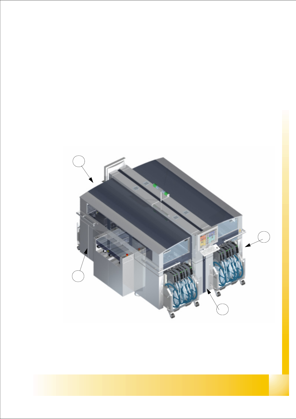
the figure below shows the position of the units which create and distribute the supply voltages
needed to operate the system
– power supply unit (pos. 1)
– section distributor section 2 (pos. 2)
– pneumatic unit (pos. 3)
– section distributor section 4 (pos. 4)
Fig. 4.1 - 1 Siplace X main units
2
3
1
4
1 - 4
Student Guide SIPLACE X
4 Services to the machine Edition 09/2005
4
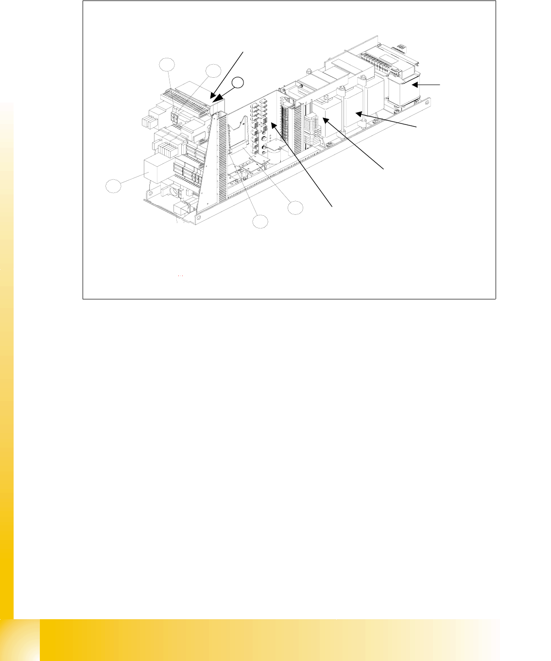
4.2 Overview power supply
Fig. 4.2 - 1 main power supply unit identical in original - and ’A’ version of the HF-Machine
Legend
(1) DC/DC Converter 24 V (4) Fuse F5 (10A) for star axis
(2) DC/DC Converter 5 V and additional 24V (5) Fuse F11(1A) for inrush current limiter
(3) Safety combination relay K6 (SSK) (6) Unloading thrush L20
1
2
3
4
5
main distributor main
power supply
Inrush current limiter:
a: transformer: EST
b: servo: Ess
transformer T
2
transformer T1
T1
T2
Fuse F61 - fuse F142
6