SiplaceX4_en.pdf - 第327页
1 - 1 1 S tudent Guide SIPLACE X Edition 09/2005 7 T win-Head 11
1 - 10
Student Guide SIPLACE X
7 Twin-Head Edition 09/2005
10
7.2.4 Height reference run
With this function we check the correct nozzle type which is programmed.
The nozzle length is taken to calculate the pick up and placement height for the following place-
ments.
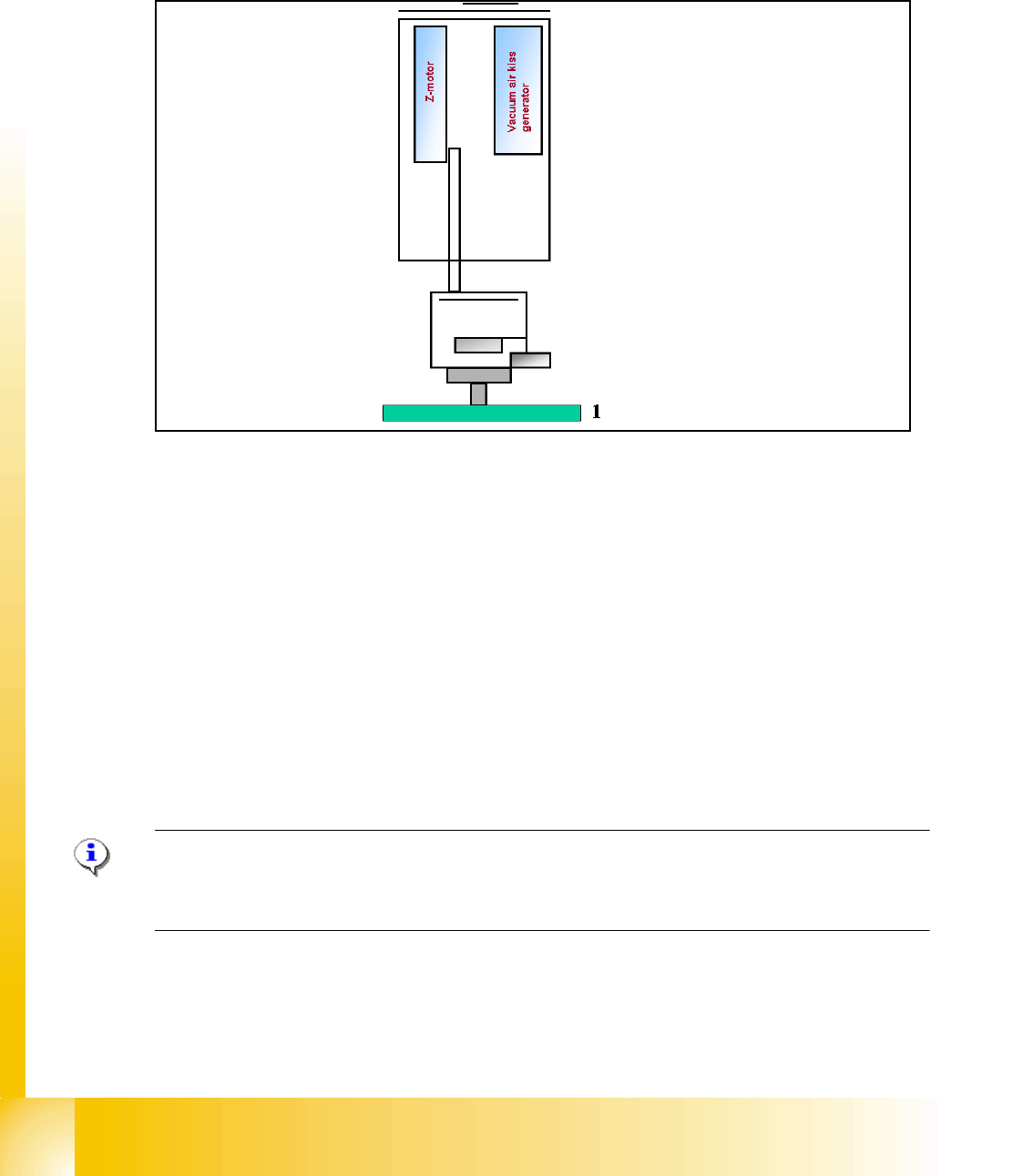
Fig. 7.2 - 4 Measure nozzle height
1. Top of fixed conveyor rail
– The gantry moves the placement heads above the fixed conveyor rail.
– The Z-Axis module 2 positioned downwards.
– The vacuum-, Air kiss generator regulate the vacuum. The reference value for closed vacuum
is calibrated in the SITEST with a standard nozzle 518.
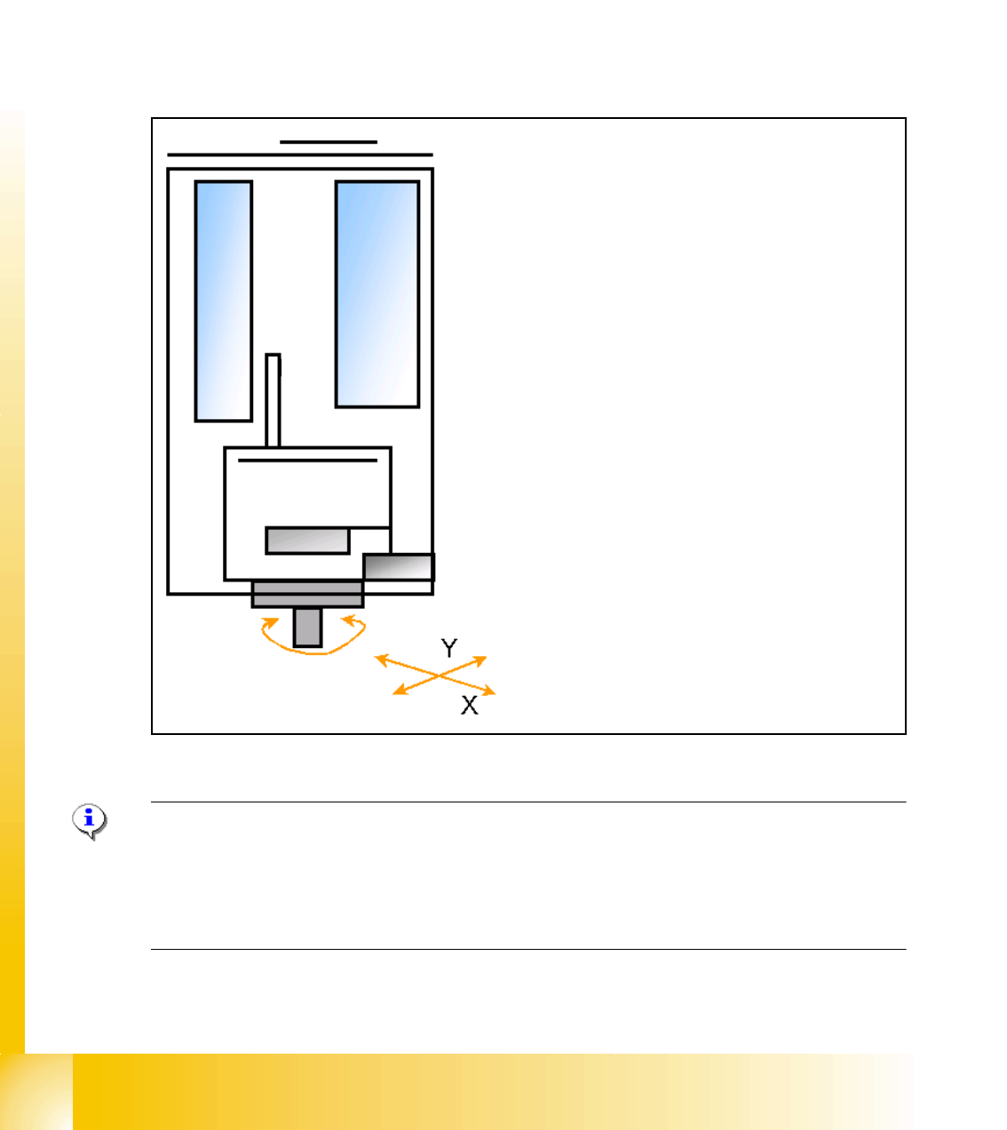
– From the travel range of the Z-Axis is the TWIN-head height calculated referring to the nozzle
type.
– Now the same happen with module 1.
– The maximum length tolerance is 0,4 mm: If the length difference is too high an error message
is displayed.
Please Note
Both modules are measured at the same position of the PCB-Transport! This TWIN-Reference run
happen parallel to the C&P-head reference run at the other placement area.

1 - 12
Student Guide SIPLACE X
7 Twin-Head Edition 09/2005
12
7.3.2 Placement principle Twin-head
During PCB-transport time wait the gantry at theoretical fiducial position to execute PCB-position
recognition (and bad mark recognition) after clamping. With " Whispering down the machine"
gantry 3 (at PA2) center only 2 fiducials of PCB recognition.
Than the TWIN-head start to collect one component with module 1 and one component with mod-
ule 2. Than follows a centering sequence for this two components.
7.3.3 Prepare pick up process module 1
Please Note:
For more accuracy the first five components centered above the IC camera in 0° and 180° at each
PCB board (SW 504). With the SW 505 we will check the offset between nozzle and IC/ FC cam-
era via a fiducial near the IC/FC camera after a defined time of 3 min. The fiducial is on a metal
plate and this plate is fixed between the camera and machine frame.
Z-
M
o
t
o
r
D-Motor
– PCB-position recognition and Ink dot recogni-
tion.
– Start X / Y Axis to Pick up position at feeder
track.
– Start D Axis to set the Pick up angle during
X / Y positioning.
– communication to comp. table ‘Feeder ready’
opens component flap.