SiplaceX4_en.pdf - 第104页
1 - 28 S tudent Guide SIPLACE X 3 Communication and Control Edition 09/2005 28 3.3.13 Communication X-Feeder The Communication betwe en the Feeder Control unit (FCU) and each X- Feede r is carried out via a CAN bus. This…
1 - 27
Student Guide SIPLACE X
Edition 09/2005 3 Communication and Control
27
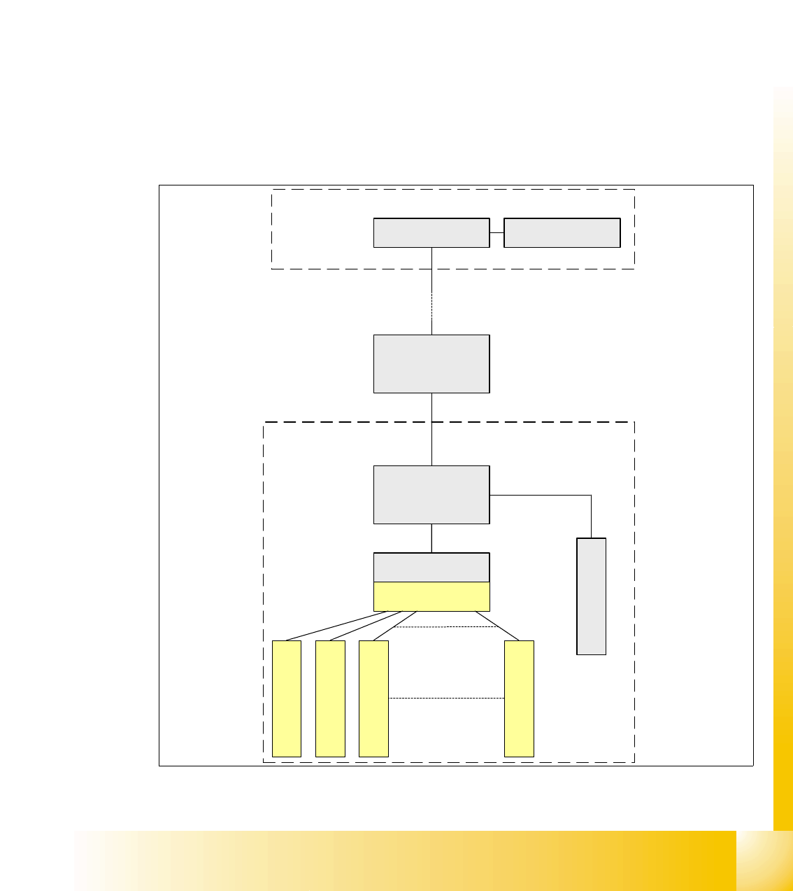
3.3.12 Communikation C&P 20 Head
The TQM –moduel on the head interface C500 is communicate via the CAN Bus (1M/Baud) to the
Machine controller.
The communication from the head interface to the C&P20 head is carried out with an additional
CAN Bus. Which sed the data with 125KBaud. (in Future 500kBaud)
The 20 DP - axes are controled via the „DP- Master" on the motherboard. So the machine CAN
Bus send 4 commands:
– Start the DP axis after Pick up/Placement (Pick up angle/Placement angle)
– Start the DP axis after Vision (Correction angle)
– Wait DP axis before Vision (Position commando not allowed)
– Wait DP axis before Pick up/Placement (Position commando not allowed)
Fig. 3.3 - 22 CAN-Bus controlled head function on the C&P 20 head
Computer Unit
Head processor
C500
COM Board
Vacuum/air kiss
generator
Machine- CAN Bus
(1MBaud)
Head- CAN Bus
(125KBaud/
500KBaud)
DP Master
Motherboard
C&P 20 Head
DP - drive 20
DP - drive 1
DP - drive 2
DP - drive 3
Intermediate
distributor
MC
1 - 28
Student Guide SIPLACE X
3 Communication and Control Edition 09/2005
28
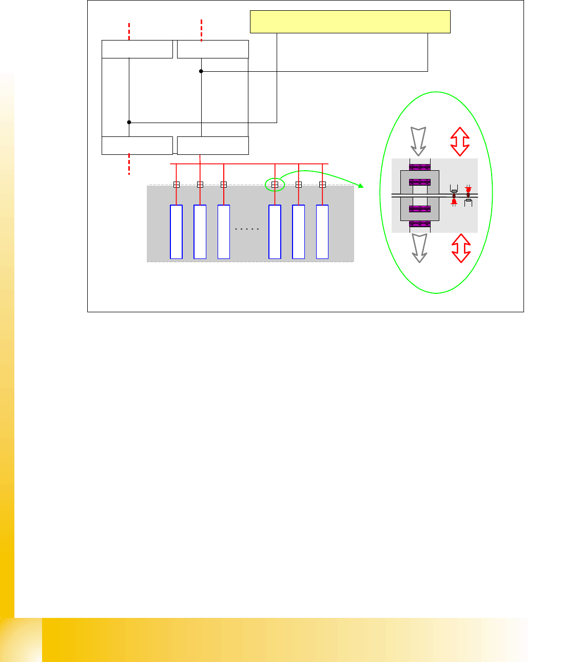
3.3.13 Communication X-Feeder
The Communication between the Feeder Control unit (FCU) and each X- Feeder is carried out via
a CAN bus. This CAN bus is only responsible for the communication between FCU and X-Feeder
and machines CAN bus controlled the "Feeder Can Bus".
Fig. 3.3 - 23 Communication X-Feeder
The data and power supply from the FCU to each feeder is contactless.
SIPLACE
X-Serie
Feeder
Feeder
Feeder
Feeder
Feeder
Feeder
Feeder-CAN Bus
BE-Wagen
(COT)
Power Data
Power Data
Machine CAN Bus
FCU Location 1
C
O
M
U
n
i
t
x
6
p
n
x
7
p
n
FCU Location 2
FCU Location 3FCU Location 4
1 - 5
Student Guide SIPLACE X
Edition 09/2005 3 Communication and Control
5
3.4 Axis control
3.4.1 Position measuring system
3.4.1.1 Track signals and Zero pulse signal
Our Axes systems consists of the following parts.
– Axis controller board with VC 3 Controller
– Servo amplifier
– Motor
– Position measuring system with Incremental- scale and -encoder
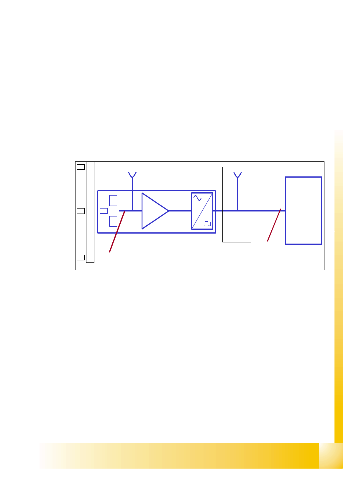
Fig. 3.4 - 1 Principle circuit for position measuring systems
Legend
The closed-loop control system of an axis is detecting the position directly at the moving element
of the axis. The position measuring system generates an analoge signal when the encoder moves
over the scale. By standard an amplifier, a multiplication circuit and digitalization is integrated in
the encoder case. A test connector is normally available at the next interface board, or the digital
signals are measurable at the Track A / B and Zero pulse output of the SIPLACE Axis Tester.
At the HFand Siplace X machine the track signals are the only feedback from the Axis to the con-
trol unit. This means any fault on the track signals may influence the Axis control; the Gantry axes
immediately stops at a fault; the head axes finish the positioning to target before showing a track
signal error.
(1) Incremental scale with zero pulses (2) Incremental encoder for track A / B and Zeropulse
signals (O-pulse.)
(3) Analoge signal output and amplifier (4) Electronic signal multiplication and signal digita-
lization
(5) Test output digital signals (6) Axis controller
A
B
A /A
B /B
0 -impuls .
/0-im
p
uls .
0 -impuls
1
2
3
4
5
6