SiplaceX4_en.pdf - 第205页
1 - 1 1 S tudent Guide SIPLACE X Edition 09/2005 5 Gantry 11 5.3.2.1 Adjustment s BERO‘s On each axis are two BERO‘s in stalled , which need a dista n ce about 0,4 mm to the m etal actuat or . The meta l actuator are ins…
1 - 10
Student Guide SIPLACE X
5 Gantry Edition 09/2005
10
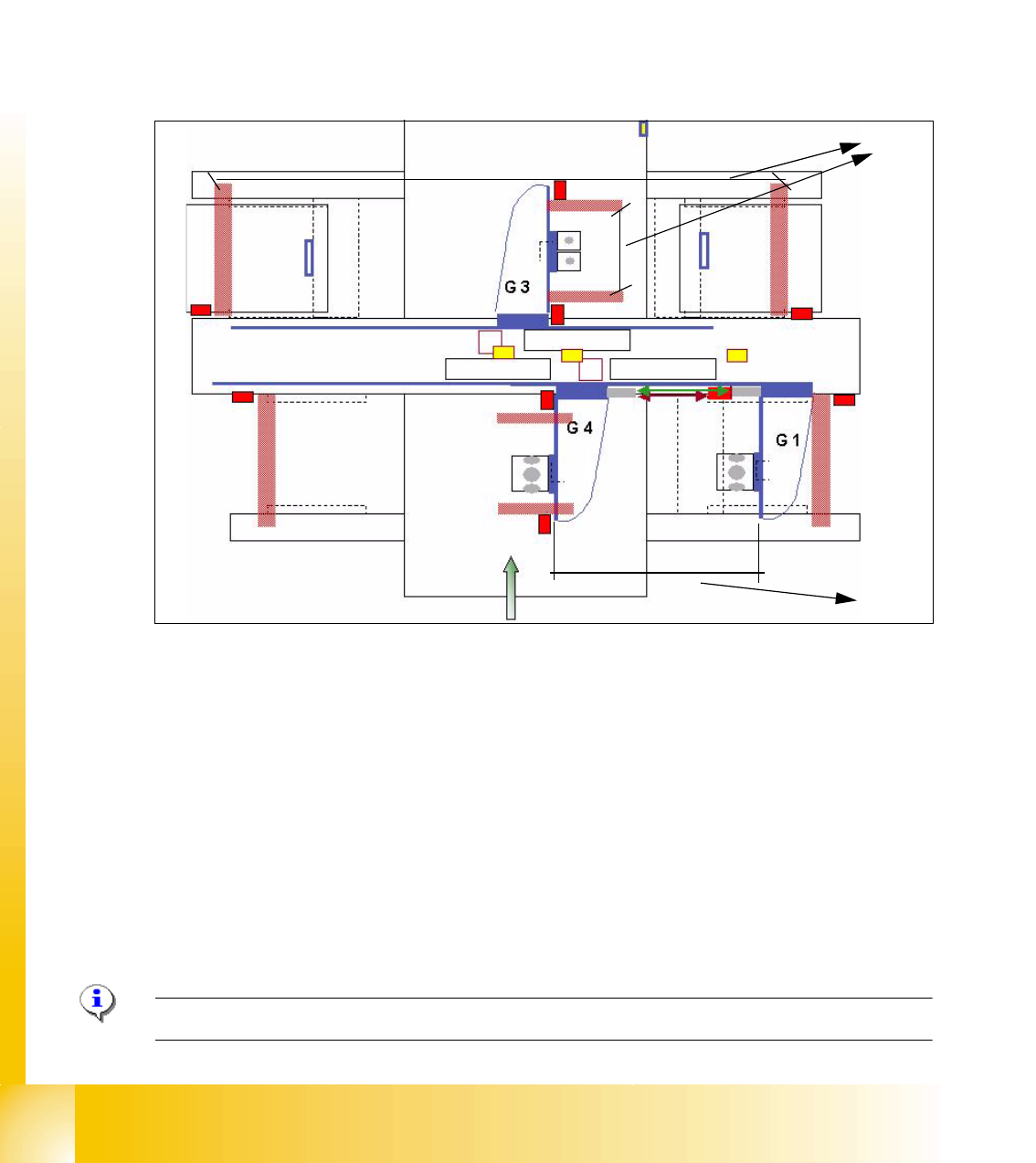
5.3.2 Travel range and velocity monitoring X- and Y- Axes on the X3
The travel range of the X- and Y-axes will be determined automatically with Sitest program. That
means, during calibration of travel range the gantry 3 went as far as possible into its minimum and
maximum position. Corresponding the description (see travel range HF) a safety space in front of
the hardware limit switch is calculated. At HF 3 machine we have two gantries in the placement
area 1 so the Y-axis of the gantry 1 went to the minimum position and the Y-axis of gantry 4 went
to the maximum position. After that we calculate the minimum position for gantry 4 according min.
pos. of gantry 1. The maximum position for gantry 1 we calculate on the result of maximum pos.
of gantry 4.(see below)
Fig. 5.3 - 2 Travel range X- and Y-axes X3 machine
(1) The calculation of the travel range for the X-axes on gantries 1 / 3 / 4 and Y-axes from the
gantry 3 is the same as the HF machine.
(2) The travel range for the y-axes on the gantries 1 and 4 are calculated partly. That means, the
Y-axis of Gantry 1 moves into the minimum position and the Y-axis of gantry 4 moves into the
maximum position. The calculation is:
Maximum position gantry 1 = Maximum position gantry 4 - 480mm (gantry width) - 20mm
safety space. (On the X4 is the travel range according to the gantry 2)
Minimum position gantry 4 = Minimum position gantry 1 + 480mm (gantry width) + 20mm
safety space. (On the X4 is the travel range according to the gantry 3)
(3) Safety space approx. 20mm
Please Note: For adjust the Anti Crash board see 5.3.4.
1
2
3
1 - 11
Student Guide SIPLACE X
Edition 09/2005 5 Gantry
11
5.3.2.1 Adjustments BERO‘s
On each axis are two BERO‘s installed, which need a distance about 0,4 mm to the metal actuator.
The metal actuator are installed on the left and right side from the incremental scale. Adjust cor-
rectly the distance with a
feeler gauge of 0,4 mm. After this adjustment calibrate the travel range
for the respective axis with the Sitest program.
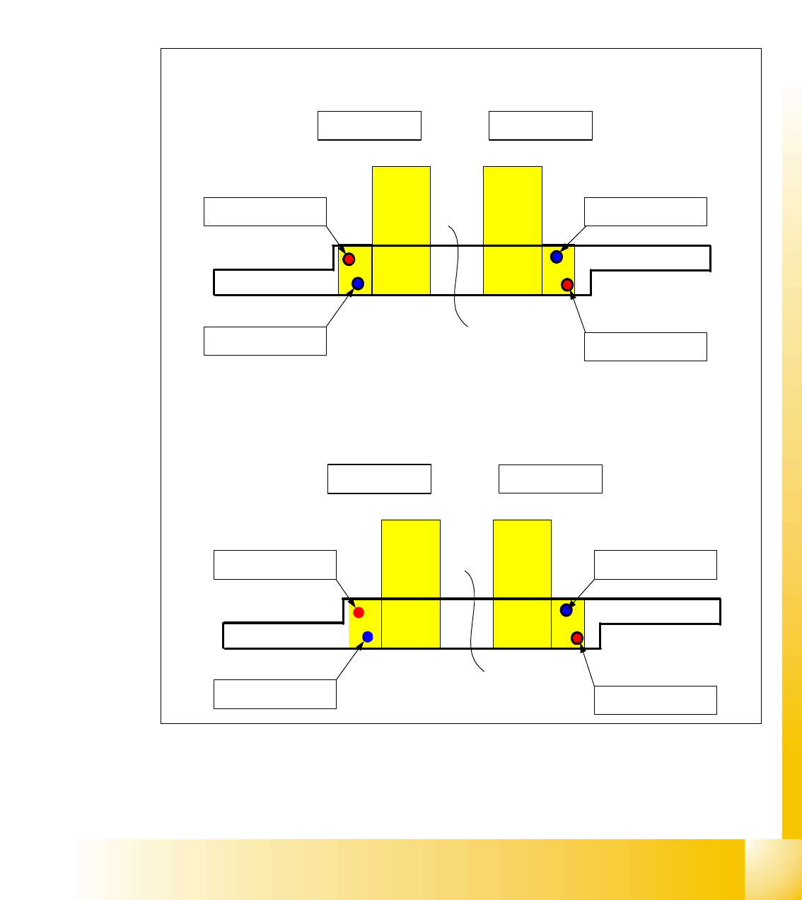
5.3.2.2 Description of the BERO‘s on the Y-Axis
Fig. 5.3 - 3 Positions of the BERO‘s depend on the gantries
– Theoretical position of the BERO‘s if gantry 2 available.
Triggering plate Y - Axes SIPLACE X
for Placement area 1
Gantry 4 Gantry 1
Reference - BERO
Gantry 4
BERO - Limit switch
Gantry 4
Reference - BERO
Gantry 1
BERO - Limit switch
Gantry 1
Triggering plate Y - Axes SIPLACE X
for Placement area 2
Gantry 2 Gantry 3
Reference - BERO
Gantry 2
BERO - Limit switch
Gantry 2
Reference - BERO
Gantry 3
BERO - Limit switch
Gantry 3
1 - 12
Student Guide SIPLACE X
5 Gantry Edition 09/2005
12
5.3.3 Description of the PCB boards on the Gantry
The PCB board which are described in this chapter are basically identical on each gantry,
independent from the head configuration. The adjustment of the gantry identification and
CAN Bus - Terminator will make via the DIP Switches on the head interface.
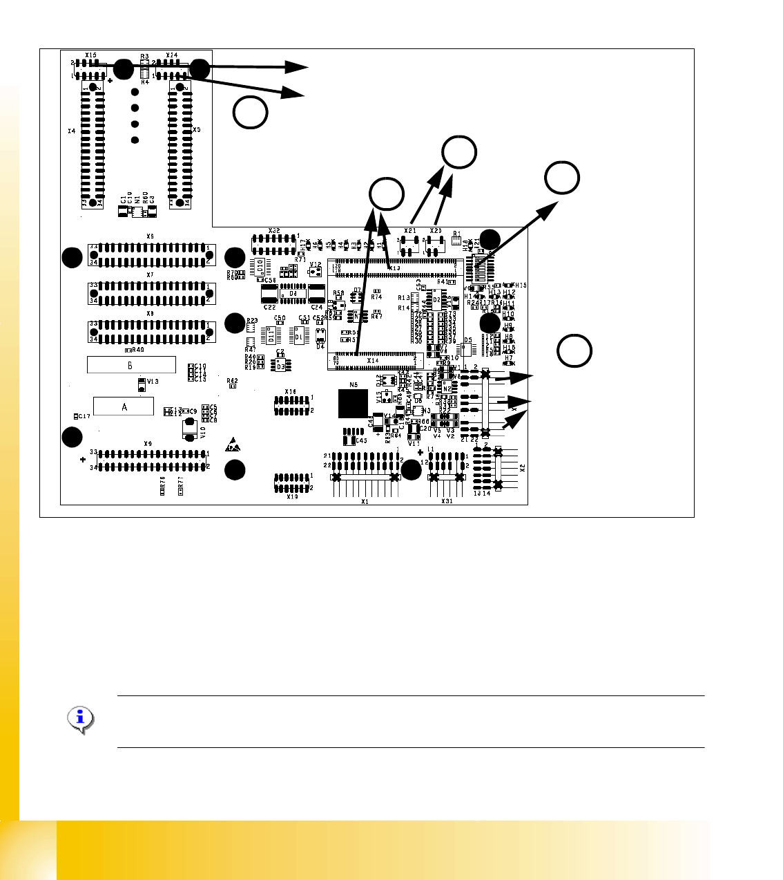
5.3.3.1 Head interface C500
Fig. 5.3 - 4 Headinterface (C500)
1. X16 Temperature sensor X-Axis, BERO‘s Travel range X-Axis
2. X15 Connector for incremental encoder X-Axis (X24 connector digital track signals X-Axis)
3. X13 / X14 Connector for 16 Bit Prozessor board (TQM module)
4. DIP switch
5. X20/X21 both connectors can you use to connect the temperature sensors from the head plate.
Please Note:
The DIP Switch configuration for the gantry configuration is decribed in chapter Gantry.
X15
X24
Temp.sensor X-Axis
BERO‘s Travel range
X-Axis
3
2
1
4
DIP Switch
5