SiplaceX4_en.pdf - 第446页
1 - 14 S tudent Guide SIPLACE X 9 Component handling Edition 09/2005 14 9.2.3.5 Mounting of Docking unit The docking unit is fixed with a special screw to the machine so that the accuracy for picking up of small componen…
1 - 13
Student Guide SIPLACE X
Edition 09/2005 9 Component handling
13
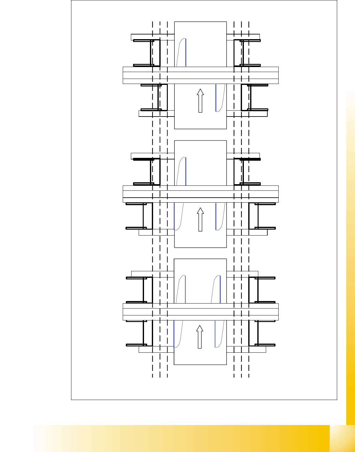
Fig. 9.2 - 5 Positions of the docking unit
Portal 1
Portal 3
Portal 4
Transportrichtung
Siplace X 3
Portal 1
Portal 3
Portal 4
Transportrichtung
Siplace X 4
Portal 2
Portal 1
Portal 2
Transportrichtung
Siplace X 2
Position docking unit
3 2 1
Position docking unit
1 2 3
3 2 1
Position docking unit
1 2 3
Position docking unit
1 - 14
Student Guide SIPLACE X
9 Component handling Edition 09/2005
14
9.2.3.5 Mounting of Docking unit
The docking unit is fixed with a special screw to the machine so that the accuracy for picking up
of small components from the COT is guaranteed. These screw had to be fixed first before the
other screws when mounting the docking unit. (Necessary in case of changing the docking unit
COT to MTC 2 or vise versa).
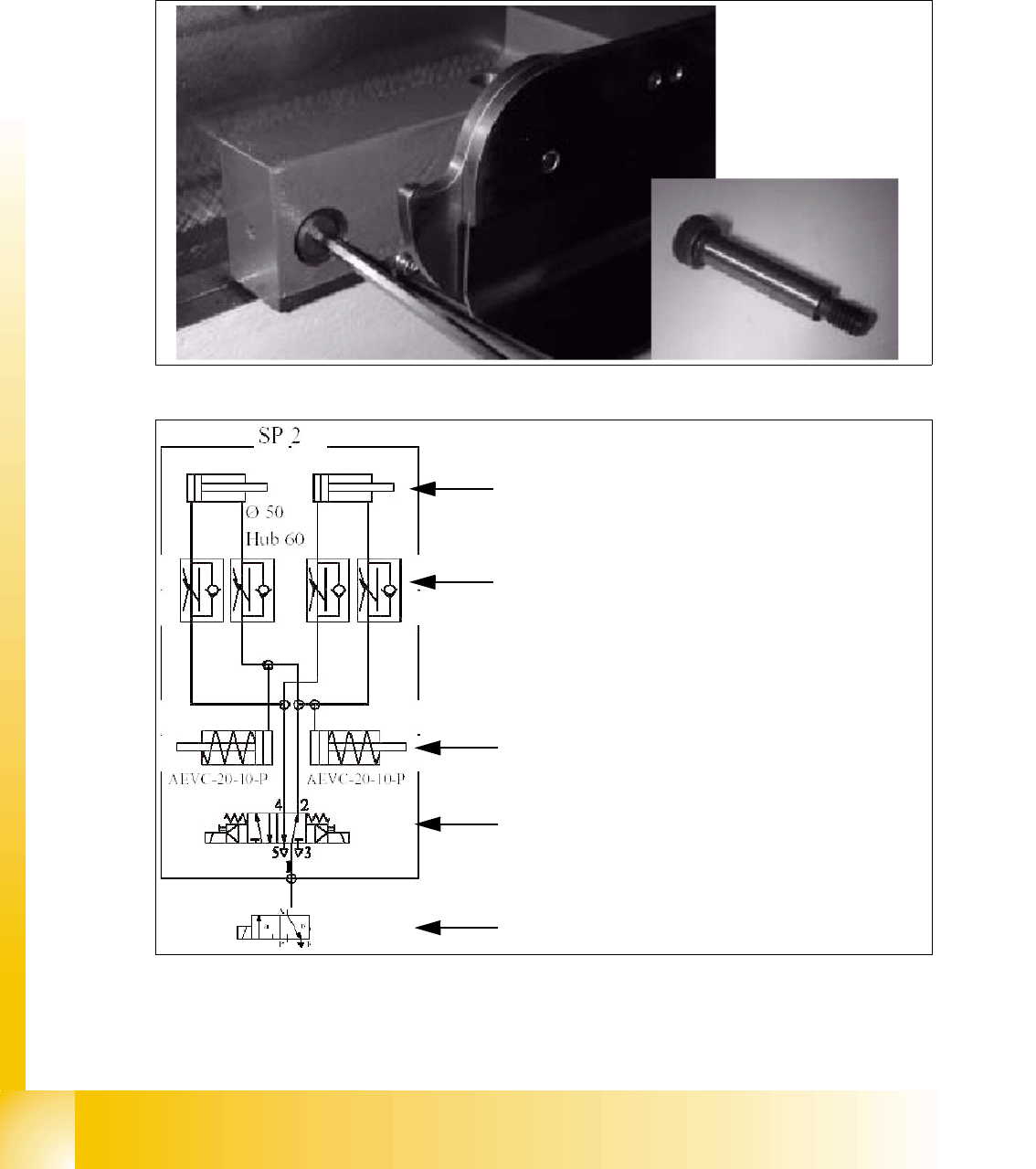
Fig. 9.2 - 6 Special screw on the docking unit
Fig. 9.2 - 7 Pneumatic diagram docking unit
Pneumatic cylinder for move the cam disks. That
means the component table plate will move hori-
zontal 43mm and 20 mm vertical into the machine.
Throttle valves for adjust the speed of the pneu-
matic cylinders (Time adjustment). The time for ad-
just should be approx. 2-3 sec.for dokking and
undocking the COT. Check the time without COT.
Pneumatic cylinders for ejection the COT during
the undocking procedure.
5/2 Way valve for control the pneumatic cylinder.
Safety valve in case of electrical faults
1 - 15
Student Guide SIPLACE X
Edition 09/2005 9 Component handling
15
9.2.4 Adjustment the COT height
NOTE:The Adjustment of the COT height is in general identical for S- and X- tables.
This task requires 2 more persons to increase and decrease the COT height.
CAUTION:
Use always the eye-bolt to fix the component plate on the S-table, independend if you increase
or reduce the component table height, otherwise you may hurt your fingers.
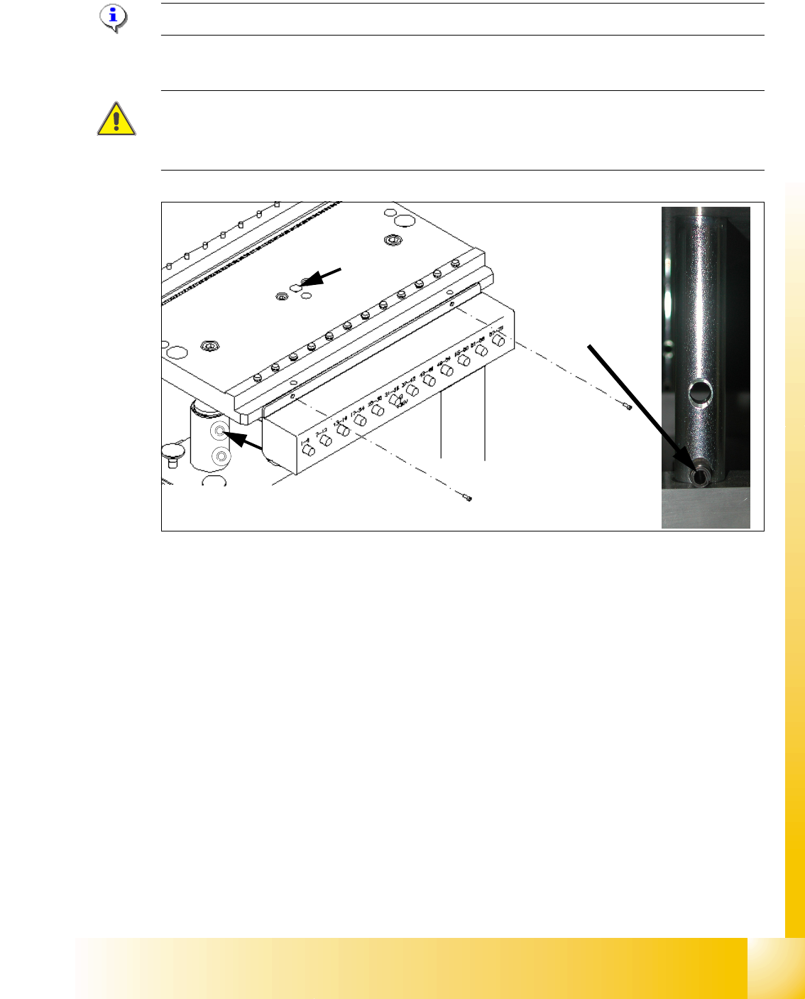
Fig. 9.2 - 8 Adjusting the COT height
Legend
Increasing and reducing the COT height 9
➠ Attach the hooks of the lifting device to the eye-bolt (1) and fix the lifting plate (S-Table).
➠ For the X-Table the second person lift up the aluminum plate (table plate).
➠ Raise the component table top part until to rich the desired position of the height from the com-
ponent table.
➠ Then remove the 2 cotter pins (2) from the left and right sleeve shaft.
➠ Move the table plate in the correct height.
➠ Put back the 2 cotter pins (2) into the drilling hole of the sleeve shaft.
➠ Now, COT height is adjusted.
(1) Drilling hole for eye-bolt 2. Hole for the cotter pins
(1)
(2)
S- table
X- table