SiplaceX4_en.pdf - 第431页
1 - 43 S tudent Guide SIPLACE X Edition 09/2005 6 Collect&Place-Head 20 43 SITEST : 6 ➠ "Select "C&P heads" ==> "Select head" ==>"Axis functions" ==> "Select Z-axi…
1 - 42
Student Guide SIPLACE X
6 Collect&Place-Head 20 Edition 09/2005
42
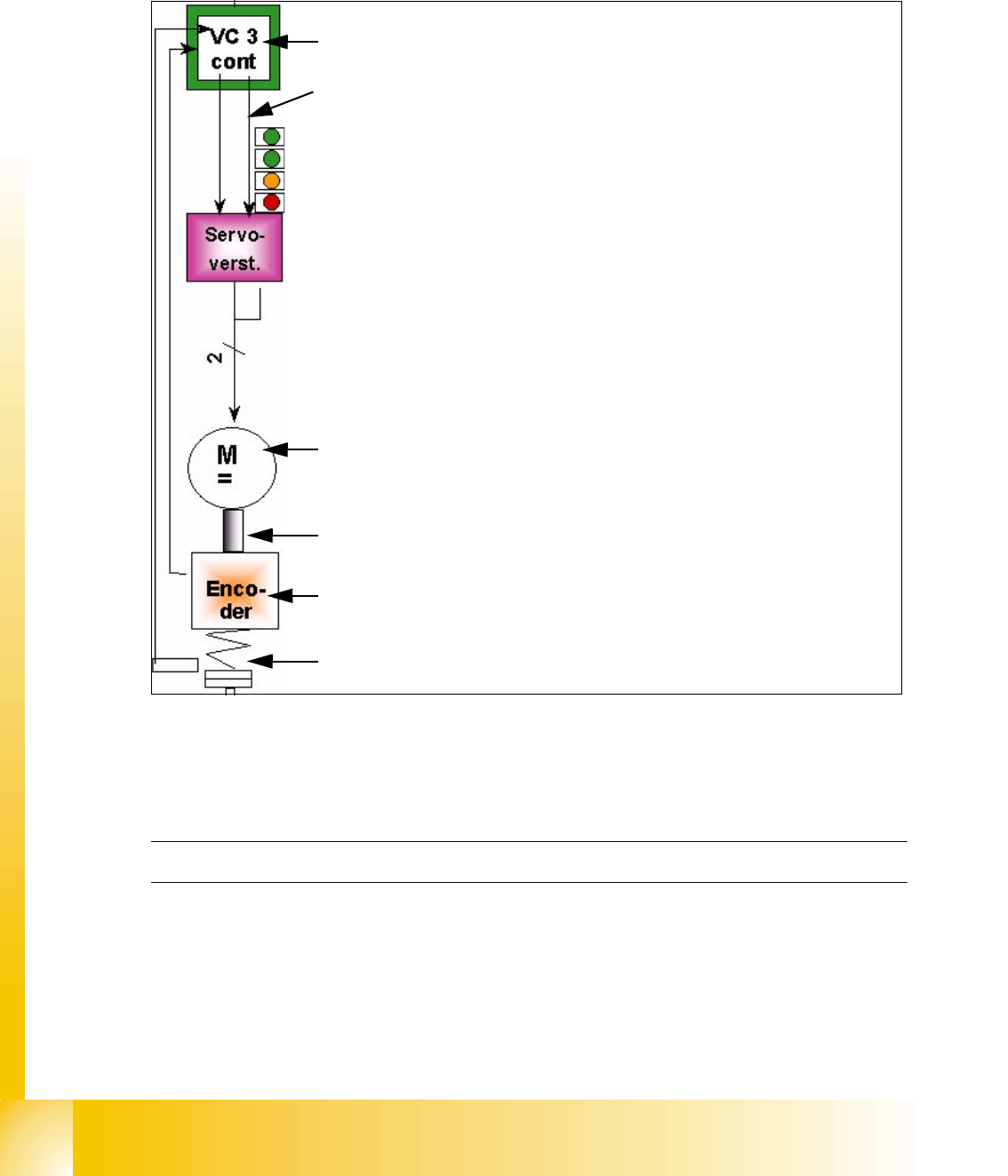
6.3.4 Axis control Z-Axis
The Z-axis is driven with a DC servo motor. The control of the axis occurred with one control si-
gnals of the VC3 controller I
nom "W" and I nom "U" = 0. The intermediate circuit voltages is
approx. 24V.
Fig. 6.3 - 6 Axis control Z-Axis
6.3.4.1 Check the dynamic Z-Axis
6.3.4.2 Test setup
Please Note:The test setup for the Z-Axis is the same as the Star-Axis
The positioning time for the Z-Axis is 30ms +/-3ms (6 segment C&P head) and 24ms, -1 ms of the
12 segment C&P head.
The positioning time C&P 20 for the same 15 mm distance is approx.
20 ms. The nom. distance should be 10mm within approx. 16ms.
– Move the gantry to the calibration tool pocket (Sitest button) and start the dynamic
check.
Axis card A363 with VC 3 Controller (VC = Velocity Commutation)
Control signal I
nom "W"
LED‘s on the Servo amplifier:
– Power supply ON
– Servo enable, if the the enable signal from the axis board available.
– Display R.M.S. current limiter shorter than 2,5 s.
– Error: Overvoltage, -current, -temperature or Nominal current-over-
stepping longer than 2,5 sec.
Servo board control directly the 3~AC (DC) motor.
3 phase (DC C&P6/12) motor.
Between the motor and the incremental encoder exist a fixed mechanical
combination.
Incremental encoder: transmit the exact position of the axis via the track
signals.
Elastic mech. Combination (Belt) and light barrier below, for the fast
recognition of the lower position.
1 - 43
Student Guide SIPLACE X
Edition 09/2005 6 Collect&Place-Head 20
43
SITEST: 6
➠ "Select "C&P heads" ==> "Select head" ==>"Axis functions" ==> "Select
Z-axis" ==> "Continuous run Z-axis" ==> "Select DIGIT for display" ==>"Edit: Target position
20000 digit and Position mode = absolut" ==> "Sart".
➠ If necessary, press the START button.
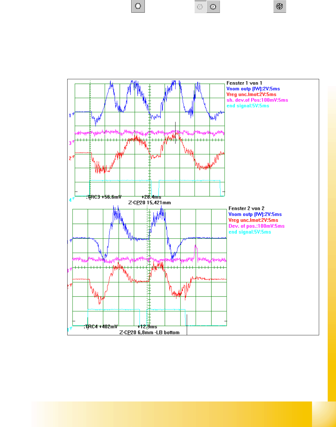
6.3.4.3 Example for C&P 20 Z- axis dynamic with the control signal of the Vnom. output
Fig. 6.3 - 7 Dynamic signals Z-Axis excample 15mm distance / example bottom Z-axis in calibration tool pocket
Legend
(1) Control signal (Axis testbox V nom.) (2) Uncommutated Current signal Vreg
(3) Position of deviation (4) End signal
1
st
Positioning here always up-
wards
2
nd
Positioning here always
downwards.
6,8 mm Positioning with the Z-
Axis into the calibration tool po-
cket.
15,4 mm Positioning with the Z-
Axis into the free space.
1 - 44
Student Guide SIPLACE X
6 Collect&Place-Head 20 Edition 09/2005
44
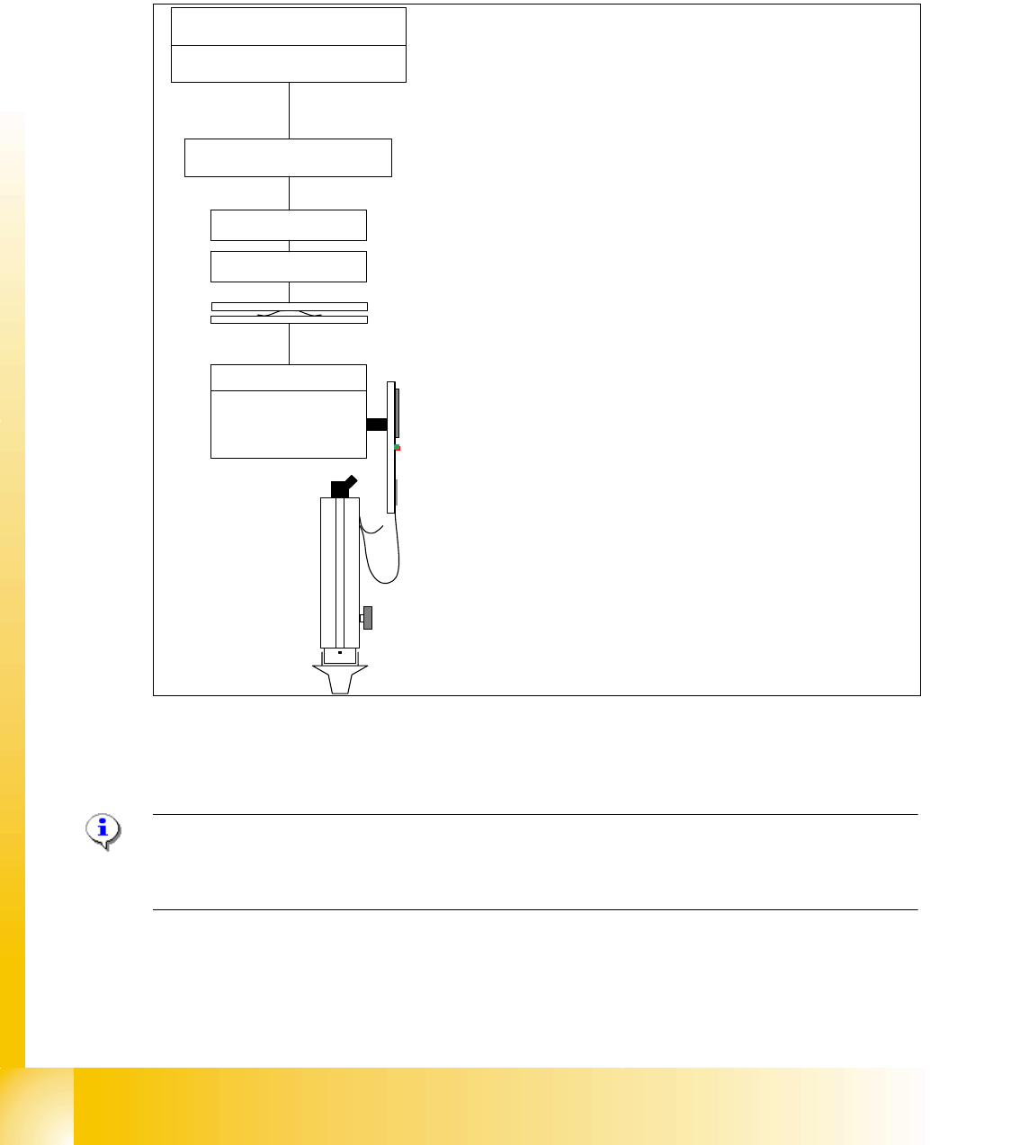
6.3.5 Axis control DP-Axis
The DP axis is driven with a DC servo motor. The control of the axis happen at the integrated DP-
control board connected to DP-mother board.
No stepping motor for swivel in /out is necessary for the C&P20 head.
Fig. 6.3 - 8 Axis control DP-Axis on one segment of the C&P 20 head
6.3.5.1 Check the dynamic DP-Axis
Please Note:
NO test points for the DP-Axis dynamic check are available on C&P 20 head. The on board control
is optimized on the Segement. It is replaced in any kind of error.
MC
head board / TQM module
µP 'DP-tasks'
head adapter
COM board
distributor board
Motherboard
DP-Master
CAN-Bus
head CAN-Bus
E
(nergie)
D (ata)
transformer
(
collector ring)
Fixed
rotary
DP-control board
DP-drive with
Encoder and
Motor
(and Vacuum-air kiss channel)
20 times
The MC transmit the activation commands
with the machinen CAN-Bus to the processor
on the headboard.
The processor activate with 4 DP-Tasks and
the ’head-CAN-Bus system with
>Head adapter,
>distributor board,
> the collector ring of the E/D-translator
to the ’Motherboard with the DP-Master.
The movement / dynamic of the DP-Motors in
the Segment is controlled on the DP-control-
board. Positioncounting pulses came fron an
integrated HALL-Incremental encoder.