SiplaceX4_en.pdf - 第156页
1 - 10 S tudent Guide SIPLACE X 4 Services to the machine Edition 09/2005 10 Unit s Identification Cont act V olt ages F6 fuse (10A) Z- and DP-axis; DP Motors C&P20 (DC/ DC converter in the Axisunit), 1-phase. 1, 2 3…

1 - 9
Student Guide SIPLACE X
Edition 09/2005 4 Services to the machine
9
Units Identification Contact Voltages
X100 main power supply L1, L2, L3 3 x 204 VAC / 3 x 380 VAC
3 x 400 VAC / 3 x 415 VAC
X102 service socket
L3, N, PE
115 VAC / 220 VAC / 230 VAC / 240 VAC
Z1 line filter L1, L2, L3 3 x 204 VAC / 3 x 380 VAC
3 x 400 VAC / 3 x 415 VAC
Q1 main switch 1, 3, 5 u.
2, 4, 6
3 x 204 VAC / 3 x 380 VAC
3 x 400 VAC / 3 x 415 VAC
Q2 motor circuit breaker 1, 3, 5 u.
2, 4, 6
3 x 204 VAC / 3 x 380 VAC
3 x 400 VAC / 3 x 415 VAC
L20 unloading thrush L1, L2, L3 3 x 204 VAC / 3 x 380 VAC
3 x 400 VAC / 3 x 415 VAC
K1 main contactor 1, 3, 5 u.
2, 4, 6
3 x 204 VAC / 3 x 380 VAC
3 x 400 VAC / 3 x 415 VAC
K2 contactor (voltage built-up
of the intermediate circuit
voltage for X/Y/Star axes)
1, 3, 5 u.
2, 4, 6
3 x 177 VAC
K3 contactor (voltage built-up
of the intermediate circuit
voltage for X/Y/Star axes)
1, 3, 5 u.
2, 4, 6
3 x 177 VAC
K4 contactor (voltage built-up
of the intermediate circuit
voltage for X/Y/Star axes)
1, 3, 5 u.
2, 4, 6
3 x 177 VAC
K5 contactor software release
is ON)
A1(+)– A2 (-)
1, 3, 7 and
2, 4, 8
24VDC
24 VDC to GND
24 VDC to GND
K6 (SSK) safety combination L+, X1,X3, X5
13, 33
23
24 VDC to GND
32VDC to GND
F1 fuse service socket (6A);
1-phase
1, 2 115 VAC / 220 VAC
230 VAC / 240 VAC
F2 fuse co-table (32A);
3-phase
1, 3, 5 u.
2, 4, 6
3 x 36 VAC
F4 fuse (32A) X- / Y-axis;
3-phase.
1, 3, 5 u.
2, 4, 6
3 x 177 VAC
F5 fuse (10A) star-axis;
1-phase
1, 2 145 VDC to GND

1 - 10
Student Guide SIPLACE X
4 Services to the machine Edition 09/2005
10
Units Identification Contact Voltages
F6 fuse (10A) Z- and DP-axis;
DP Motors C&P20 (DC/DC
converter in the Axisunit),
1-phase.
1, 2 39 VDC to GND
F7 fuse (6A) secundary circuit;
3-phase
1, 3, 5 u.
2, 4, 6
3 x 230 VAC
F8 fuse (6A) PCB-transport;
1-phase
1, 2 33 VDC to GND
F10 fuse (16A) rectifier V7 and
V70; 3-phase
1, 3, 5 u.
2, 4, 6
3 x 39 VAC
F11 fuse (1A) inrush current
limiter
1-phase
1, 2 33,6 VDC to GND
F12 fuse (6A) illumination
1-phase
1, 2 52 VDC to GND
F13 fuse (3A) monitor;
1-phase
1, 2 26 VDC to GND
F14 fuse (6A) Y-motor cooling
device
1-phase
1, 2 26 VDC to GND
F21 / F22 /
F23
fuse (T6,3A) unloading
thrush L20
1, 2
3 x 204 VAC / 3 x 380 VAC
3 x 400 VAC / 3 x 415 VAC
F61 / F62 fuse (10A) rectifier U4
1, 2
3 x 28 VAC
F81 / F82 fuse (T10A) rectifier U5
1, 2
3 x 23,8 VAC
F111 / F112 fuse (T1A) rectifier U8
1, 2
3 x 23,8 VAC
F131 / F132 fuse (T4A) rectifier U10
1, 2
3 x 19,7 VAC
F141 / F142 fuse (T6,3A) rectifier U11
1, 2
3 x 18,7 VAC
1 - 11
Student Guide SIPLACE X
Edition 09/2005 4 Services to the machine
11
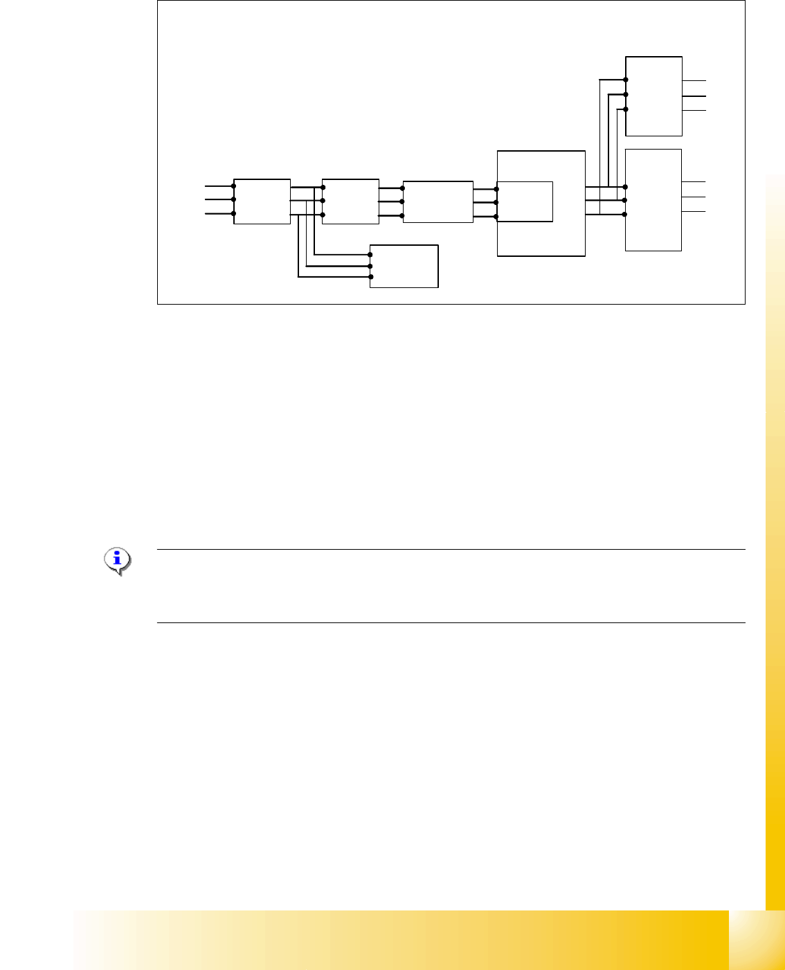
4.2.4.1 Input Voltage
Fig. 4.2 - 5 input voltage
Legend
Q1: main switch
Q2: motor circuit breaker
K1: main contactor and inrush current limiter for T1
T1: transformer 1
T2: transformer 2
L20: unloading thrush
Note:
After the transformer T1 and T2, the main power potential end and only secundary voltages supply
the machine
Q1
Q2
K1
3 phase
U
V
W
T1
U
V
W
T2
3x 230 V
Ínrush current
limiter for T1
L1
L2
L3
power
filter
L20