SiplaceX4_en.pdf - 第522页
1 - 17 S tudent Guide SIPLACE X Edition 09/2005 1 1 Sitest 17 1 1.2.5 Operation for calibra ting the entire machine NOTE : see precondit ion for calibr ating, ch apter 1 1.2.2 – St art Sitest Fig. 1 1.2 - 3 Calibrating t…
1 - 16
Student Guide SIPLACE X
11 Sitest Edition 09/2005
16
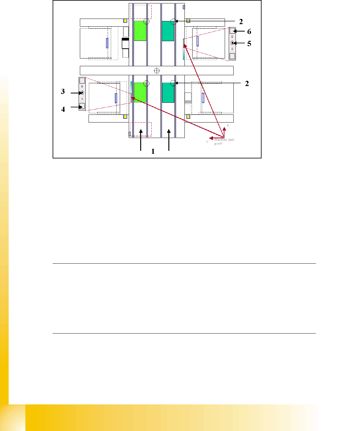
11.2.4 Calibration positions in the machine
Fig. 11.2 - 2 Top view of machine
Key:
(1) Transport direction
(2) Fixed PCB corner BB 1/ 2 Track 1 and 2
(3) Machine zero point BB 1
(4) Calibration position BB 1 (depend on the head type)
(5) Machine zero point BB 2
(6) Calibration position BB 2 (depend on the head type)
Note:
Some calibrations require that you attach nozzles on the placement heads.
Use nozzles of type
956 for C&P6/12, 1235 for C&P20 and for the Twin head 517. Make sure that
all nozzles have been attached correctly, otherwise measuring will lead to incorrect results.
If you need to, place the calibration tool into the "calibration pocket". (Fig. 11.2 - 2).
Before you place the calibration tool, make sure that it is clean. Also, be sure that you insert it into
the "calibration pocket" with its print of the fiducial structure on the bottom. 11
1 - 17
Student Guide SIPLACE X
Edition 09/2005 11 Sitest
17
11.2.5 Operation for calibrating the entire machine
NOTE : see precondition for calibrating, chapter 11.2.2
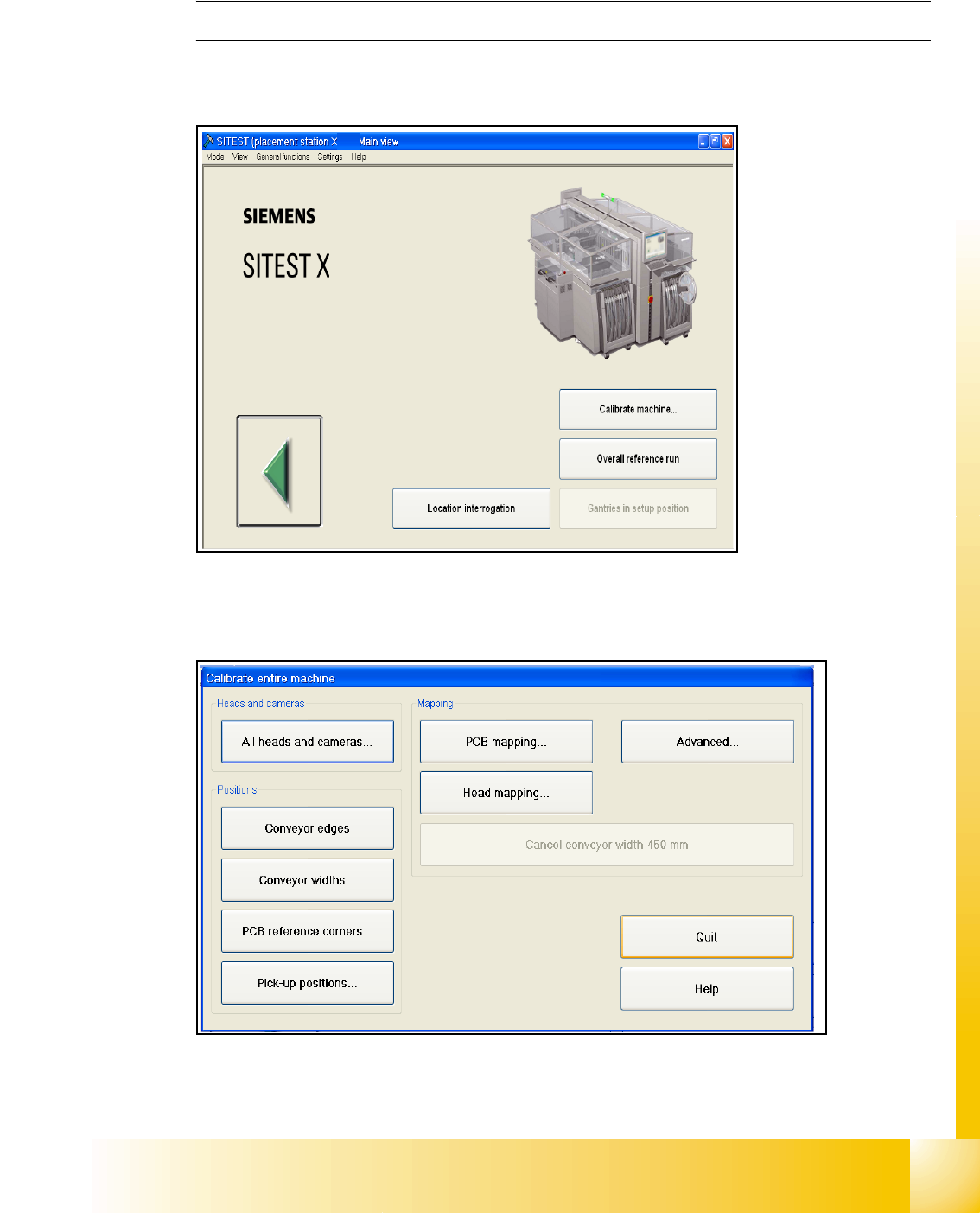
– Start Sitest
Fig. 11.2 - 3 Calibrating the entire machine
– Choose "Calibrate machine..."
Fig. 11.2 - 4 Main menu for calibrating the entire machine
– Choose "All heads and cameras..."
1 - 18
Student Guide SIPLACE X
11 Sitest Edition 09/2005
18
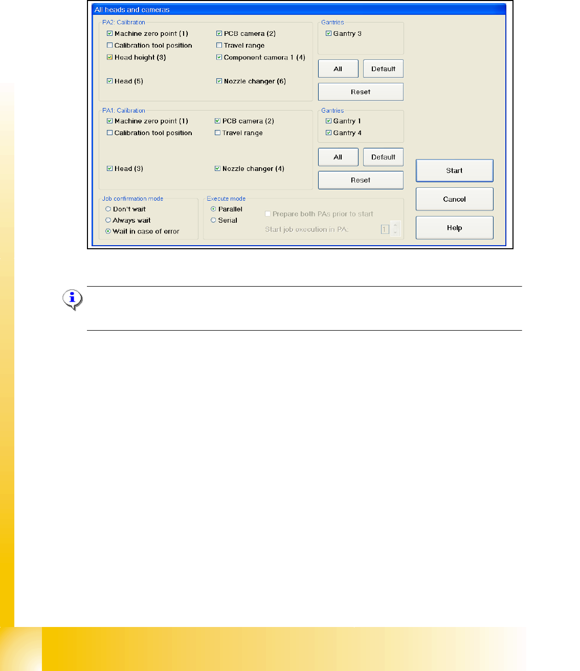
11.2.6 ALL heads and cameras
Depends of the configuration the X - machine about the heads on Gantry 1 and Gantry 2 the cal-
ibration seqeuence is different.
Fig. 11.2 - 5 All heads and cameras (default settings)
Note:
If you want to calibrate only one placement area deactivate all points in the field PAx Calibration
and Gantries.
The Calibration steps for the C&P head and Twin head see Fig. 11.2 - 6. and Fig. 11.2 - 7.
➠ Select all points which you must calibrate
➠ Select the execute mode parallel or serial ( For the parallel mode prepare both placement ar-
eas, calibration tool and nozzles)
➠ Select the job confirmation mode
➠ Press the START button
Job confirmation mode 11
Don't wait: When this function is activated, the next job is carried out immediately after a job is
completed or an error occurs, without waiting for confirmation.
Always wait: When this function is activated, the next job is not carried out until confirmation is
received after a job is completed or an error occurs. You must click the Next job button to do this.
Wait in case of error: When this function is activated, the job is interrupted if an error occurs and
the next job is not carried out until confirmation is received. You must click the Next job button to
do this.