SiplaceX4_en.pdf - 第565页
1 - 22 S tudent Guide SIPLACE X 12 Siplace X - Head M odularity Edition 09/2005 22 Notes
1 - 21
Student Guide SIPLACE X
Edition 09/2005 12 Siplace X - Head Modularity
21
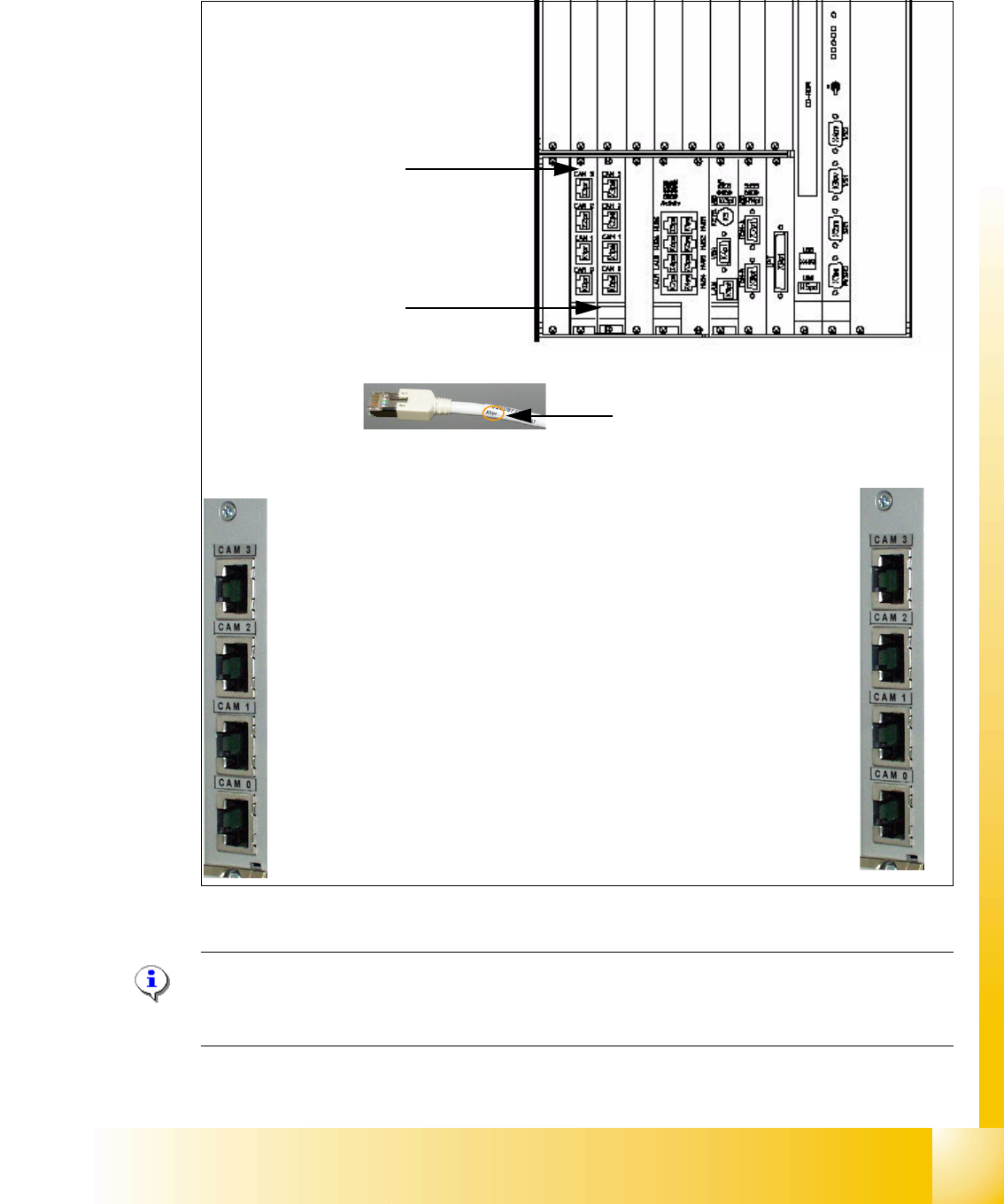
12.8 Connectors on the Hotlink Board (Computer unit)
Note:
Don‘t connect the Hotlink Cable which are not used!!!
Don‘t confused the Hotlink Cable with Twisted Pair Cable!!!
Hotlink- board for
cameras in PA 1
Hotlink- board for
cameras in PA 2
Label Hotlink-Cable
FC Camera in PA 1
X3pr
PCB/Component Cam-
eras in PA 1 Gantry 1
X0pr
PCB/Component Cam-
eras in PA 1 Gantry 4
X1pr
IC Camera in PA 1
X2pr
FC Camera in PA 2
X3ps
IC Camera in PA 2
X2ps
PCB/Component Cam-
eras in PA 2 Gantry 3
X1ps
PCB/Component Cam-
eras in PA 2 Gantry 2
X0ps

1 - 22
Student Guide SIPLACE X
12 Siplace X - Head Modularity Edition 09/2005
22
Notes

Student Guide SIPLACE X
Edition 09/2005 Contents
1
Chapter
Table of Contents
13 MTC 2 . . . . . . . . . . . . . . . . . . . . . . . . . . . . . . . . . . . . . . . . . . . . . . . . . . . . . . . . . . . . 1
13.1 Overview . . . . . . . . . . . . . . . . . . . . . . . . . . . . . . . . . . . . . . . . . . . . . . . . . . . . . . . . . . . . . . . . . . . . . . 1
13.1.1 General Matrix Tray Changer 2 . . . . . . . . . . . . . . . . . . . . . . . . . . . . . . . . . . . . . . . . . 1
13.1.2 Functional principles . . . . . . . . . . . . . . . . . . . . . . . . . . . . . . . . . . . . . . . . . . . . . . . . . 2
13.1.3 Occupying and numbering the tower. . . . . . . . . . . . . . . . . . . . . . . . . . . . . . . . . . . . . 4
13.1.4 Technical data . . . . . . . . . . . . . . . . . . . . . . . . . . . . . . . . . . . . . . . . . . . . . . . . . . . . . . 5
13.1.4.1 Dimensions, weight, miscellaneous data . . . . . . . . . . . . . . . . . . . . . . . . . . . . . . 5
13.1.4.2 Electrical connections. . . . . . . . . . . . . . . . . . . . . . . . . . . . . . . . . . . . . . . . . . . . . 6
13.1.4.3 Noise emission information . . . . . . . . . . . . . . . . . . . . . . . . . . . . . . . . . . . . . . . . 6
13.1.4.4 Permitted ambient conditions . . . . . . . . . . . . . . . . . . . . . . . . . . . . . . . . . . . . . . . 6
13.1.5 Safety information . . . . . . . . . . . . . . . . . . . . . . . . . . . . . . . . . . . . . . . . . . . . . . . . . . . 7
13.1.5.1 Warning and information labels on the MTC 2 . . . . . . . . . . . . . . . . . . . . . . . . . . 7
13.1.5.2 Safety instructions for transporting the MTC 2 . . . . . . . . . . . . . . . . . . . . . . . . . 12
13.1.5.3 Residual voltages at the inverters when the MTC 2 is switched off . . . . . . . . . 12
13.1.6 Safety features . . . . . . . . . . . . . . . . . . . . . . . . . . . . . . . . . . . . . . . . . . . . . . . . . . . . 13
13.1.6.1 Protective doors . . . . . . . . . . . . . . . . . . . . . . . . . . . . . . . . . . . . . . . . . . . . . . . . 13
13.1.6.2 EMERGENCY STOP button. . . . . . . . . . . . . . . . . . . . . . . . . . . . . . . . . . . . . . . 13
13.1.6.3 Protective door switches. . . . . . . . . . . . . . . . . . . . . . . . . . . . . . . . . . . . . . . . . . 14
13.1.6.4 Combination circuit breakers . . . . . . . . . . . . . . . . . . . . . . . . . . . . . . . . . . . . . . 15
13.1.6.5 Safety and signaling circuits. . . . . . . . . . . . . . . . . . . . . . . . . . . . . . . . . . . . . . . 15
13.1.6.6 Safety loops . . . . . . . . . . . . . . . . . . . . . . . . . . . . . . . . . . . . . . . . . . . . . . . . . . . 16
13.2 Construction and mode of operation. . . . . . . . . . . . . . . . . . . . . . . . . . . . . . . . . . . . . . . . . . . . . . 17
13.2.1 Incorporating the MTC in the SIPLACE station . . . . . . . . . . . . . . . . . . . . . . . . . . . . 18
13.2.1.1 CAN bus . . . . . . . . . . . . . . . . . . . . . . . . . . . . . . . . . . . . . . . . . . . . . . . . . . . . . . 18
13.2.1.2 400 V power supply . . . . . . . . . . . . . . . . . . . . . . . . . . . . . . . . . . . . . . . . . . . . . 18
13.2.1.3 EMERGENCY STOP interface. . . . . . . . . . . . . . . . . . . . . . . . . . . . . . . . . . . . . 18
13.2.2 Reference position run . . . . . . . . . . . . . . . . . . . . . . . . . . . . . . . . . . . . . . . . . . . . . . 19
13.2.3 Installation MTC 2 . . . . . . . . . . . . . . . . . . . . . . . . . . . . . . . . . . . . . . . . . . . . . . . . . . 20
13.2.4 Modules of the controller . . . . . . . . . . . . . . . . . . . . . . . . . . . . . . . . . . . . . . . . . . . . . 21
13.2.4.1 C167 controller board. . . . . . . . . . . . . . . . . . . . . . . . . . . . . . . . . . . . . . . . . . . . 22
13.2.4.2 Masterdrives. . . . . . . . . . . . . . . . . . . . . . . . . . . . . . . . . . . . . . . . . . . . . . . . . . . 23
13.2.4.3 24V power supply. . . . . . . . . . . . . . . . . . . . . . . . . . . . . . . . . . . . . . . . . . . . . . . 23
13.2.4.4 Electronics board . . . . . . . . . . . . . . . . . . . . . . . . . . . . . . . . . . . . . . . . . . . . . . . 23
13.2.4.5 Mounting plate . . . . . . . . . . . . . . . . . . . . . . . . . . . . . . . . . . . . . . . . . . . . . . . . . 24
13.2.5 Block diagrams . . . . . . . . . . . . . . . . . . . . . . . . . . . . . . . . . . . . . . . . . . . . . . . . . . . . 25
13.2.6 Installation MTC 2 . . . . . . . . . . . . . . . . . . . . . . . . . . . . . . . . . . . . . . . . . . . . . . . . . . 28
13.2.7 General works before starting the MTC 2 . . . . . . . . . . . . . . . . . . . . . . . . . . . . . . . . 29
13.2.8 Placement functions of the MTC 2 . . . . . . . . . . . . . . . . . . . . . . . . . . . . . . . . . . . . . 29