00195741-0102_UM_D1_D2_SR605_EN.pdf - 第105页
User Manual SIPLACE D1/D2 3 Technical data for the machine From software version SR.605.xx 07/2008 EN Edition 3.4 Dimensions and weig ht 105 3.4.4 Machine foot clearances 3 Fig. 3.4 - 3 Machine foot clearances
3 Technical data for the machine User Manual SIPLACE D1/D2
3.4 Dimensions and weight From software version SR.605.xx 07/2008 EN Edition
104
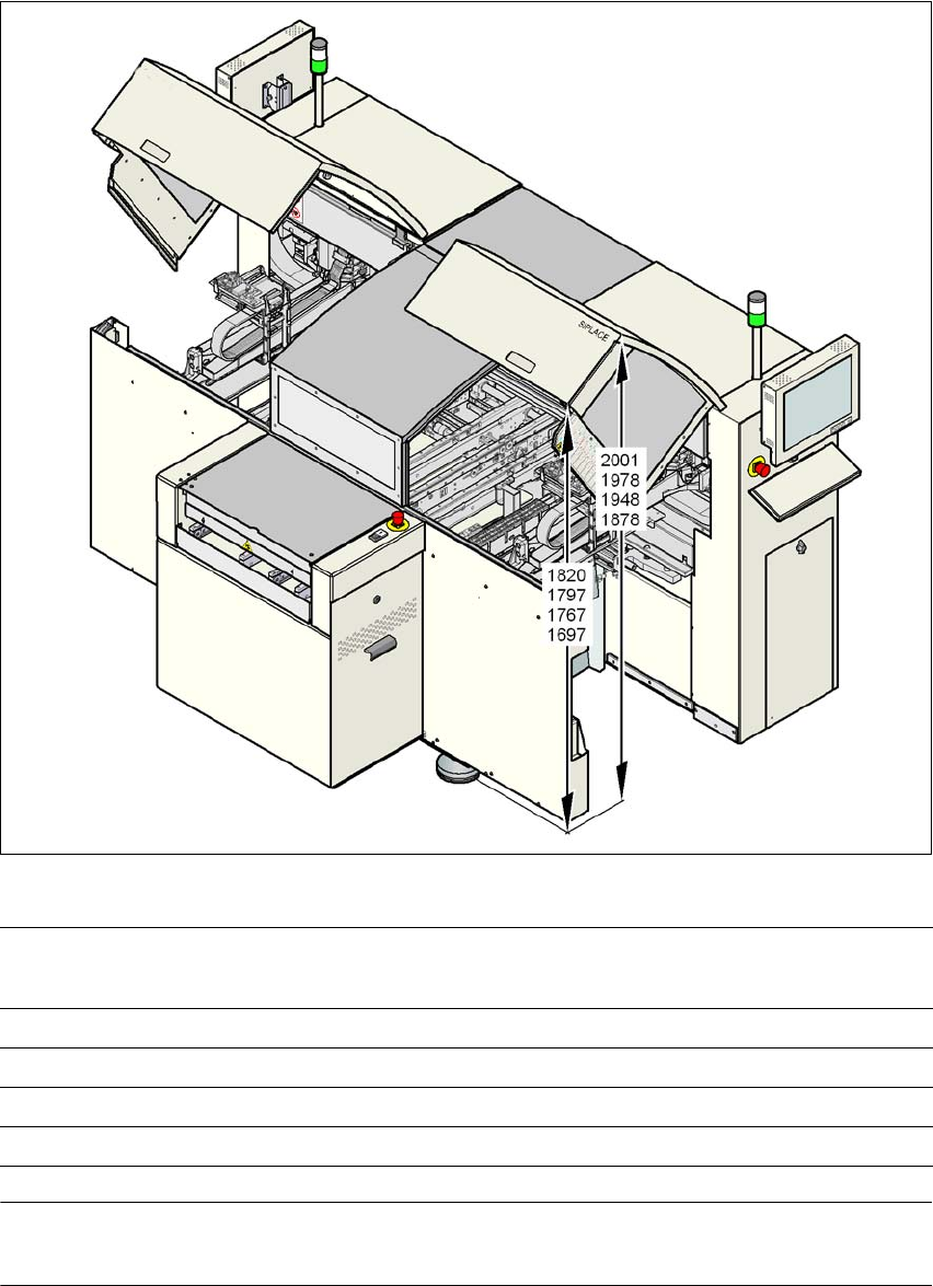
3.4.3 Height of the folded up protective cover
3
Fig. 3.4 - 2 Height of the folded-up protective cover - dimensions in millimeters
PLEASE NOTE 3
One can optionally increase the opening angle of the protective covers using other gas springs.
PCB conveyor height Height of bottom edge of the
lifted-up protective cover
Height of top edge of the lifted-
up protective cover
950 mm 1820 2001
930 mm 1797 1978
900 mm 1767 1948
830 mm 1697 1878
User Manual SIPLACE D1/D2 3 Technical data for the machine
From software version SR.605.xx 07/2008 EN Edition 3.4 Dimensions and weight
105
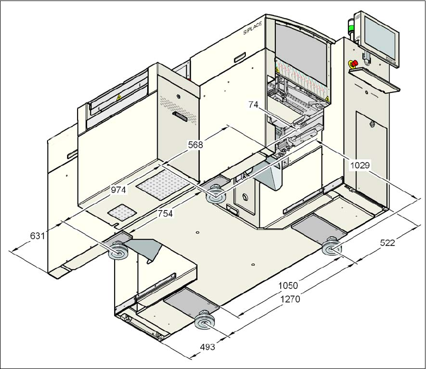
3.4.4 Machine foot clearances
3
Fig. 3.4 - 3 Machine foot clearances
3 Technical data for the machine User Manual SIPLACE D1/D2
3.4 Dimensions and weight From software version SR.605.xx 07/2008 EN Edition
106
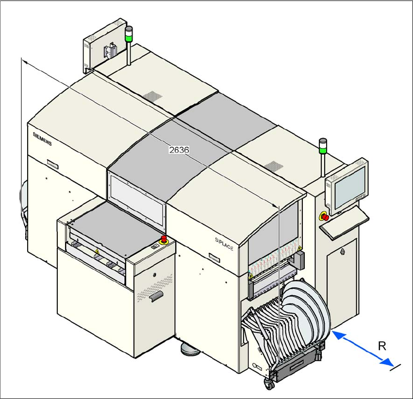
3.4.5 Maneuvring distance and distance between the component trolleys
on the D1 machine
3
Fig. 3.4 - 4 Maneuvring distance and distance between the component trolleys on the D1 machine
The distance between the component trolleys is 2636 mm.
The maneuvering distance R of the component trolley on the machine is 1200 mm.