00195741-0102_UM_D1_D2_SR605_EN.pdf - 第185页
User Manual SIPLACE D1/D2 4 Setting up and commissioning From software version SR.605.xx 07/2008 EN Edition 4.1 Transport and delivery configuration 185 4 Setting up and commissioning 4.1 T ransport and delivery configur…
3 Technical data for the machine User Manual SIPLACE D1/D2
3.11 Component trolley From software version SR.605.xx 07/2008 EN Edition
184
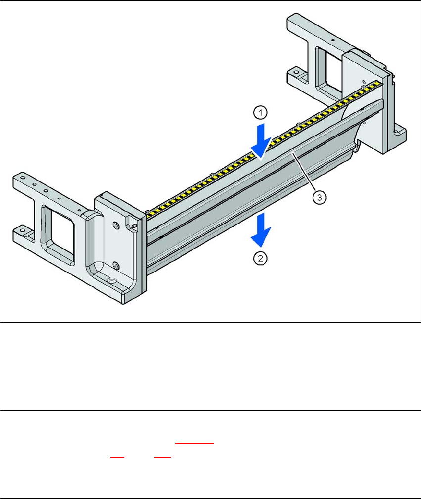
3.11.10 Used tape channel
In the standard version, the used tape channel can guide component tapes with a maximum
pocket height of 17 mm to the pneumatic tape cutter.
3
Fig. 3.11 - 13 Used tape channel with component reject bin
(1) Inlet slot for the used tapes
(2) Outlet slot for the used tape above the pneumatic tape cutter
(3) Dividing plate for tapes < 17 mm (can be removed for tapes > 17 mm)
PLEASE NOTE
– The separating plate (item 3 in Fig. 3.11 - 13
) can be removed for tape pockets higher than
17 mm (see Section 4.5
, page 227).
→ Do not position feeder modules with shallow pockets immediately beside feeder modules with
deep pockets. The used tapes could overlap and build up.
User Manual SIPLACE D1/D2 4 Setting up and commissioning
From software version SR.605.xx 07/2008 EN Edition 4.1 Transport and delivery configuration
185
4 Setting up and commissioning
4.1 Transport and delivery configuration
4.1.1 Shipping packaging
Within Europe, the machine and the CO trolleys are supplied on two pallets and wrapped in plastic
film. They will be dispatched overseas in two robust wooden crates.
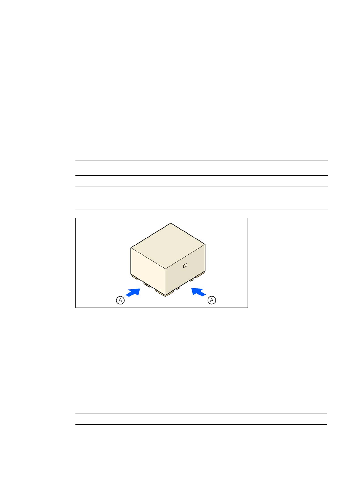
4.1.1.1 Dimensions of the shipping packaging
4
4
4
Fig. 4.1 - 1 Transport crate - dimension in millimeters
(A) Fork-lift attachment points
4.1.1.2 Weight of the machine prepared for dispatch
The following table contains the weights of the machines prepared for dispatch, including packag-
ing.
4
Crate for the machine Crate for the component trolleys
Length 2570 mm 1700 mm
Width 1860 mm 1200 mm
Height 1600 mm 1300 mm
Weight Dispatch within Europe Dispatch overseas
SIPLACE D1
SIPLACE D2
2240 kg
2258 kg
2604 kg
2622 kg
CO trolley 370 kg 450 kg

4 Setting up and commissioning User Manual SIPLACE D1/D2
4.1 Transport and delivery configuration From software version SR.605.xx 07/2008 EN Edition
186
4.1.2 Checking a delivery
→ Store the machine in the packaging until room temperature has been reached. There is oth-
erwise a risk of condensation occurring.
→ Check the delivery for damage.
→ Check the shock sensors.
→ Unpack the machine and the accessories and check the delivery for completeness (reference
delivery note).
→ Document the result in the installation report / acceptance testing report.
4.1.3 Configuration when delivered
The machine is configured as follows when delivered:
– The track on the single conveyor is set to a width of 210 mm. On the dual conveyor, the width
of conveyor track 1 is 100 mm and conveyor track 2 is 210 mm. These preset PCB conveyor
widths make it easier to remove the extension kit and conveyor on the input side of the ma-
chine when this is necessary for reasons of space in order to transport the machine.
– Both keyboards (item 1 in Fig. 4.1 - 2
) are unplugged.
– The supporting plates for the keyboards (item 2 in Fig. 4.1 - 2
) are detached.
– Both monitors (item 3 in Fig. 4.1 - 2
) are dismantled.
– Both indicator lamps (item 4 in Fig. 4.1 - 2
) are dismantled.
– All the gantry axes are fixed with shipping braces.