00195741-0102_UM_D1_D2_SR605_EN.pdf - 第225页
User Manual SIPLACE D1/D2 4 Setting up and commissioning From software version SR.605.xx 07/2008 EN Edition 4.4 A dapting the component tro lley to the PCB conveyor height 225 4.4.7 950 mm PCB conveyor height 4 Fig. 4.4 …
4 Setting up and commissioning User Manual SIPLACE D1/D2
4.4 Adapting the component trolley to the PCB conveyor height From software version SR.605.xx 07/2008 EN Edition
224
4
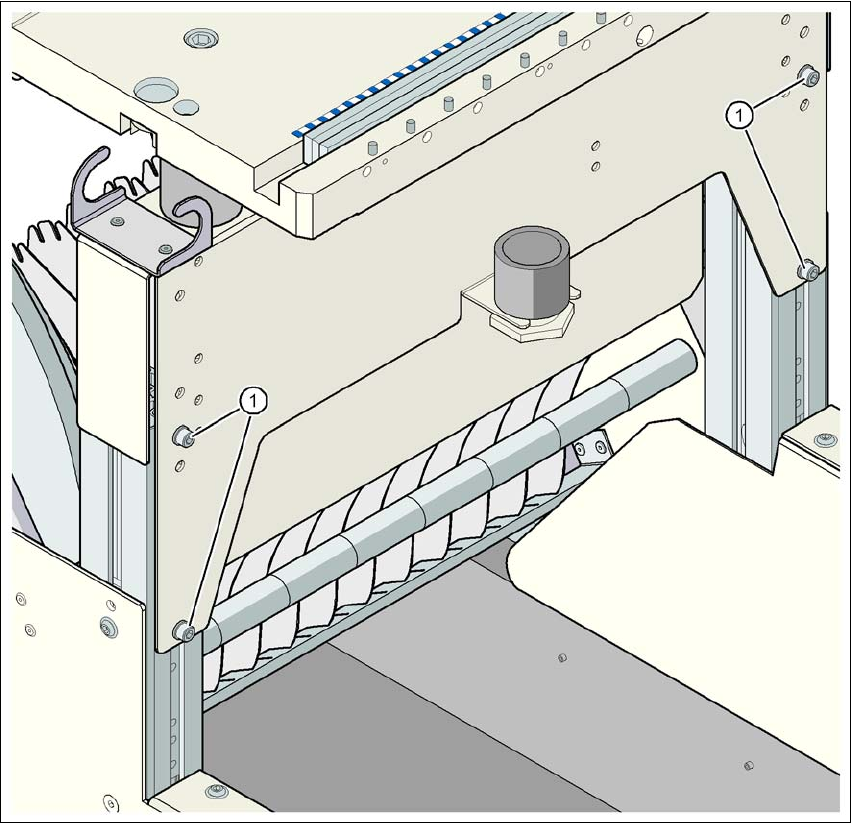
Fig. 4.4 - 7 Component trolley: PCB conveyor height 930 mm - front view, position of the hexagon socket head
screws
(1) Hexagon socket head screw M6x12 and washer (4x on the rear panel)
User Manual SIPLACE D1/D2 4 Setting up and commissioning
From software version SR.605.xx 07/2008 EN Edition 4.4 Adapting the component trolley to the PCB conveyor height
225
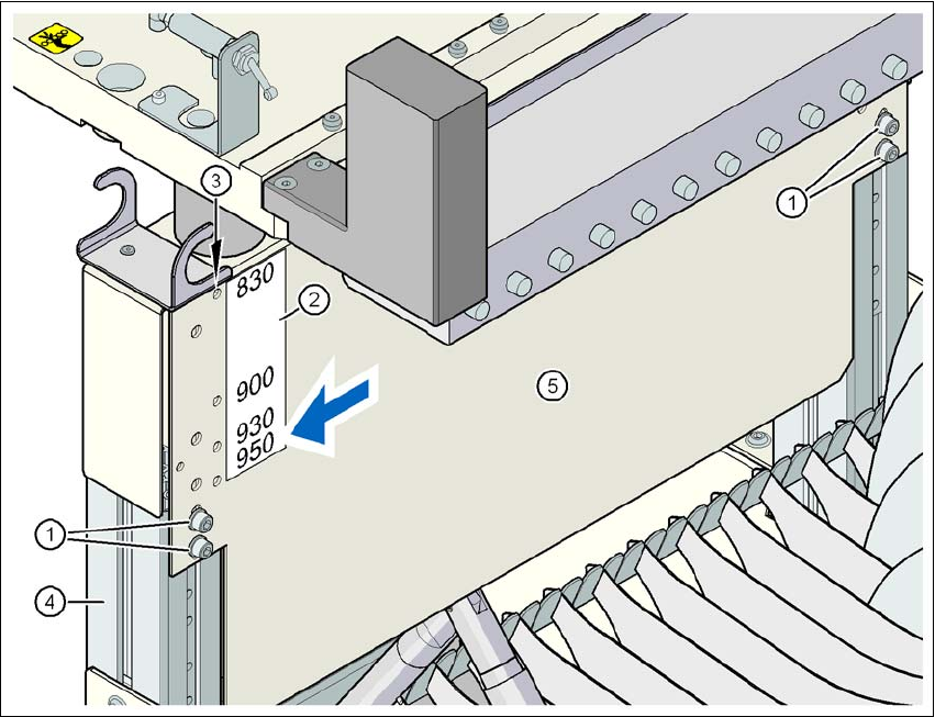
4.4.7 950 mm PCB conveyor height
4
Fig. 4.4 - 8 Component trolley: PCB conveyor height 950 mm - back view, position of the hexagon socket
head screw and check hole
(1) Hexagon socket head screw M6x12 and washer (4x on the rear panel)
(2) Sticker with the heights 830, 900, 930 and 950 mm for the check holes
(3) 4 check holes for checking the preset height. The selected height is preset correctly if the
check hole is not covered by the vertical profiled beam (item 4) (see arrow in the figure)
(4) Vertical profiled beam
(5) Jumper
4 Setting up and commissioning User Manual SIPLACE D1/D2
4.4 Adapting the component trolley to the PCB conveyor height From software version SR.605.xx 07/2008 EN Edition
226
4
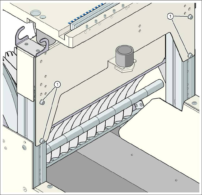
Fig. 4.4 - 9 Component trolley: PCB conveyor height 950 mm - front view, position of the hexagon socket head
screws
(1) Hexagon socket head screw M6x12 and washer (4x on the rear panel)