00195741-0102_UM_D1_D2_SR605_EN.pdf - 第180页
3 Technical data for the machine User Manual SIPLACE D1/D2 3.11 Component trolley From software version SR.605.xx 07/2008 EN Edition 180 3.1 1.7.3 Adapter plate assembly position for 930 mm PCB conveyor height PLEASE NOT…
User Manual SIPLACE D1/D2 3 Technical data for the machine
From software version SR.605.xx 07/2008 EN Edition 3.11 Component trolley
179
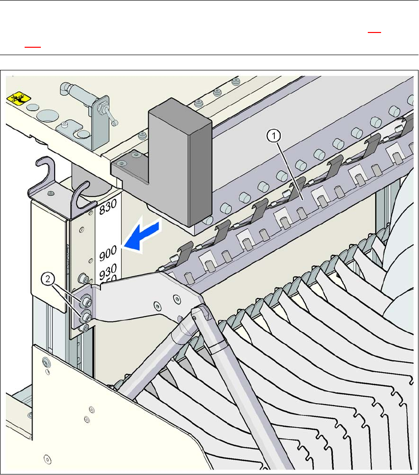
3.11.7.2 Adapter plate assembly position for 900 mm PCB conveyor height
PLEASE NOTE
The procedure for setting the height of the component trolley is described in Section 4.4
, from
page 216.
3
Fig. 3.11 - 8 Adapter plate assembly position for 900 mm PCB conveyor height
(1) Adapter plate
(2) Hexagon socket head screw, M6x20 with washer, 4 x
3 Technical data for the machine User Manual SIPLACE D1/D2
3.11 Component trolley From software version SR.605.xx 07/2008 EN Edition
180
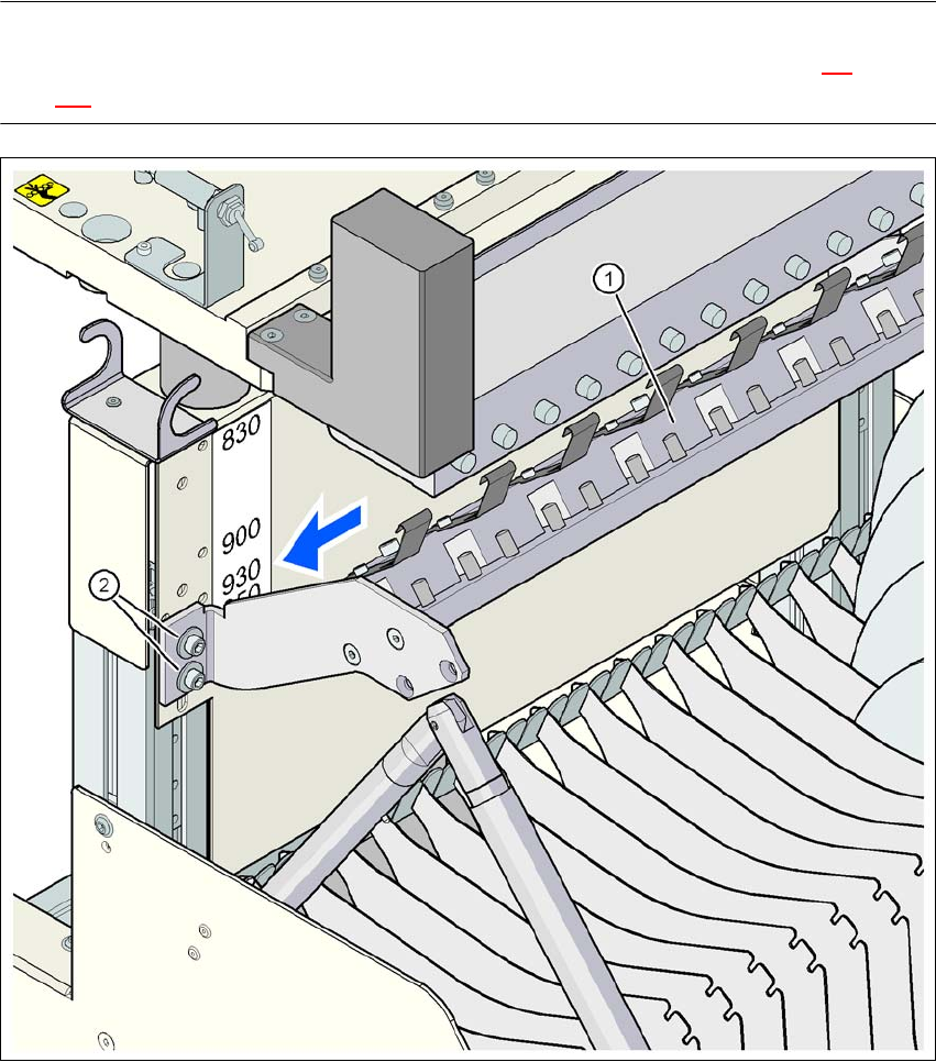
3.11.7.3 Adapter plate assembly position for 930 mm PCB conveyor height
PLEASE NOTE
The procedure for setting the height of the component trolley is described in Section 4.4
, from
page 216.
3
Fig. 3.11 - 9 Adapter plate assembly position for 930 mm PCB conveyor height
(1) Adapter plate
(2) Hexagon socket head screw, M6x20 with washer, 4 x
User Manual SIPLACE D1/D2 3 Technical data for the machine
From software version SR.605.xx 07/2008 EN Edition 3.11 Component trolley
181
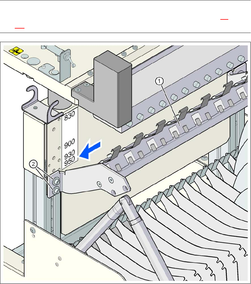
3.11.7.4 Adapter plate assembly position for 950 mm PCB conveyor height
PLEASE NOTE
The procedure for setting the height of the component trolley is described in Section 4.4
, from
page 216.
3
Fig. 3.11 - 10 Adapter plate assembly position for 950 mm PCB conveyor height
(1) Adapter plate
(2) Hexagon socket head screw, M6x20 with washer, 4 x