00195741-0102_UM_D1_D2_SR605_EN.pdf - 第178页
3 Technical data for the machine User Manual SIPLACE D1/D2 3.11 Component trolley From software version SR.605.xx 07/2008 EN Edition 178 The adapter plate is fi xed to the component tro lley with four fillister head scre…
User Manual SIPLACE D1/D2 3 Technical data for the machine
From software version SR.605.xx 07/2008 EN Edition 3.11 Component trolley
177
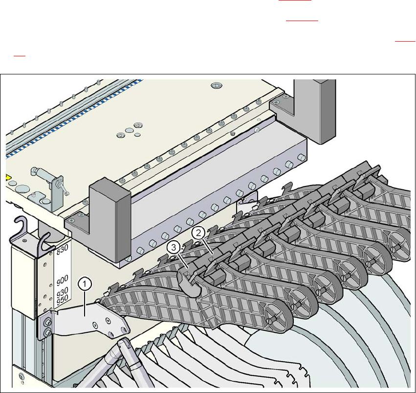
3.11.7 Reel holder for the middle tape reel on 3 x 8 mm S feeder modules
Item no. 00119846-xx Adapter plate for tape reel holder D1, D2
Item no. 00141204-xx Tape reel holder, 3 x 8 mm feeder module, V2
Item no. 00141215-xx Tape reel holder, 3 x 8 mm feeder module, V2, track 1
Type 3 x 8 mm S feeder modules transport components to the pick-up position on three feeder
tracks. The tape reels for the two outer tracks are located between the dividing plates in the tape
container. The middle tape reel is arranged over the tape reels for the two outer tracks. Use the
reel holder for the middle tape reel when more than two 3 x 8 mm S feeder modules are to be used
per component trolley.
For the middle tape reels you will also need:
– 1 adapter plate for holding the tape reel holder (item 1 in Fig. 3.11 - 6
) and
– for every two feeder modules, 1 tape reel holder (item 2 in Fig. 3.11 - 6
)
– On track 1: Tape reel holder with shortened idler pulley for 1 feeder module (item 3 in Fig. 3.11
- 6)
Fig. 3.11 - 6 Reel holder for the middle tape reel on 3 x 8 mm S feeder modules
3 Technical data for the machine User Manual SIPLACE D1/D2
3.11 Component trolley From software version SR.605.xx 07/2008 EN Edition
178
The adapter plate is fixed to the component trolley with four fillister head screws, and the tape reel
holders are inserted into the square openings in the adapter plate.
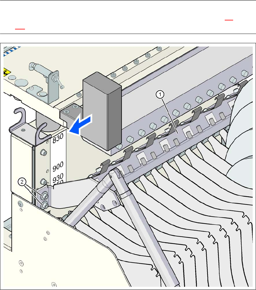
3.11.7.1 Adapter plate assembly position for 830 mm PCB conveyor height
PLEASE NOTE
The procedure for setting the height of the component trolley is described in Section 4.4
, from
page 216.
3
Fig. 3.11 - 7 Adapter plate assembly position for 830 mm PCB conveyor height
(1) Adapter plate
(2) Hexagon socket head screw, M6x20 with washer, 4x
User Manual SIPLACE D1/D2 3 Technical data for the machine
From software version SR.605.xx 07/2008 EN Edition 3.11 Component trolley
179
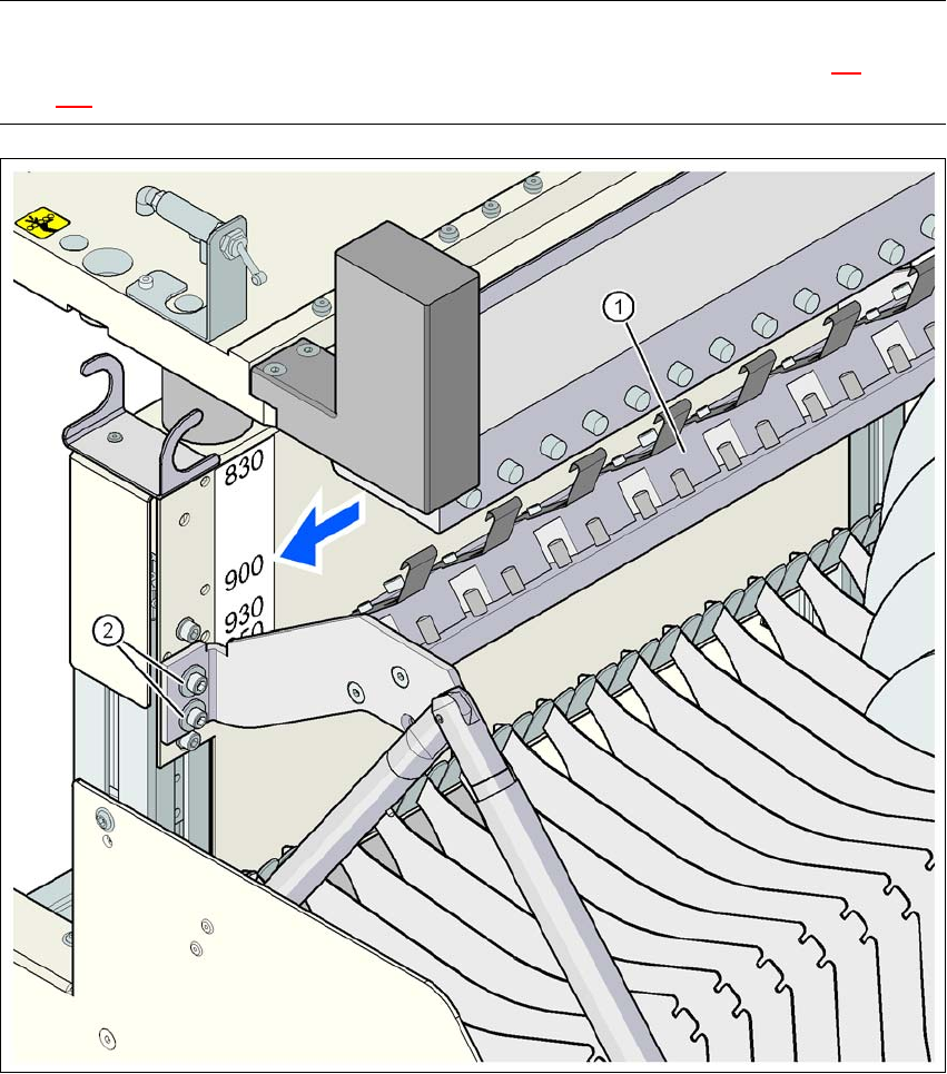
3.11.7.2 Adapter plate assembly position for 900 mm PCB conveyor height
PLEASE NOTE
The procedure for setting the height of the component trolley is described in Section 4.4
, from
page 216.
3
Fig. 3.11 - 8 Adapter plate assembly position for 900 mm PCB conveyor height
(1) Adapter plate
(2) Hexagon socket head screw, M6x20 with washer, 4 x