00195741-0102_UM_D1_D2_SR605_EN.pdf - 第211页
User Manual SIPLACE D1/D2 4 Setting up and commissioning From software version SR.605.xx 07/2008 EN Edition 4.3 Setting up the machine 211 4.3.7.3 Machine foot clearances fo r the D1 machine and WPC 4 4 4 4 Fig. 4.3 - 5 …
4 Setting up and commissioning User Manual SIPLACE D1/D2
4.3 Setting up the machine From software version SR.605.xx 07/2008 EN Edition
210
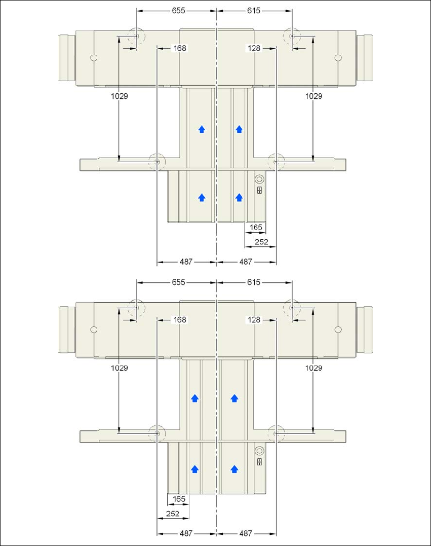
4.3.7.2 Machine foot clearances and the stationary right and left
conveyor edge for the PCB dual conveyor
4
Fig. 4.3 - 4 Machine foot clearances and the stationary right and left conveyor edge for the PCB dual conveyor in mil-
limeters
Stationary conveyor
side right
Stationary conveyor
side left
User Manual SIPLACE D1/D2 4 Setting up and commissioning
From software version SR.605.xx 07/2008 EN Edition 4.3 Setting up the machine
211
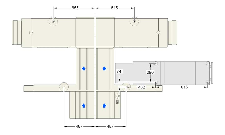
4.3.7.3 Machine foot clearances for the D1 machine and WPC
4
4
4
4
Fig. 4.3 - 5 Machine foot clearances for the machine and WPC in millimeters
4 Setting up and commissioning User Manual SIPLACE D1/D2
4.3 Setting up the machine From software version SR.605.xx 07/2008 EN Edition
212
4.3.8 Integrating the machine into the line
→ Note the warning instructions described in Section 4.3.2, page 203.
→ The tools and equipment are listed in Section 4.3.3
, page 204.
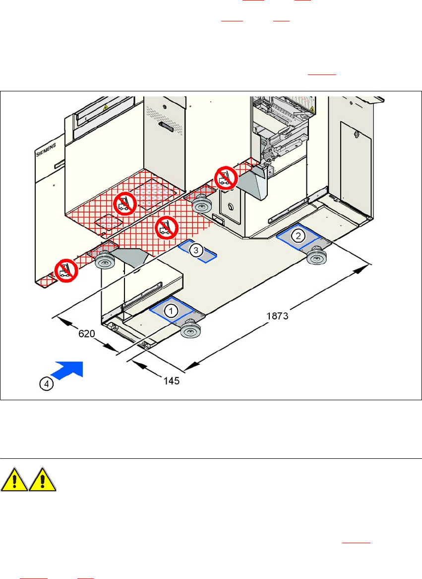
4.3.8.1 Positioning the fork lift
→ Push the forks of the fork-lift under the machine, as shown in Fig. 4.3 - 6.
4
Fig. 4.3 - 6 Machine attachment surfaces for the fork-lift - dimensions in millimeters
WARNING 4
Please note the following points before you raise the machine in order to avoid irreversible dam-
age to the machine:
→ Attach the fork-lift on the power supply side of the machine (item 4 in Fig. 4.3 - 6
).
→ Make sure that the machine attachment surfaces 1, 2 and 3 lie evenly on the fork (see Fig.
4.3 - 6
, page 212). Use wooden planks of appropriate length for support, if the fork is shorter.