00195741-0102_UM_D1_D2_SR605_EN.pdf - 第19页
User Manual SIPLACE D1/D2 1 Introduction From software version SR.605.xx 07/2008 EN Edition 1.1 Description of the machine 19 The PCBs are optically centered with the digital PCB camera . 1.1.3 Selecting the placem ent h…
1 Introduction User Manual SIPLACE D1/D2
1.1 Description of the machine From software version SR.605.xx 07/2008 EN Edition
18
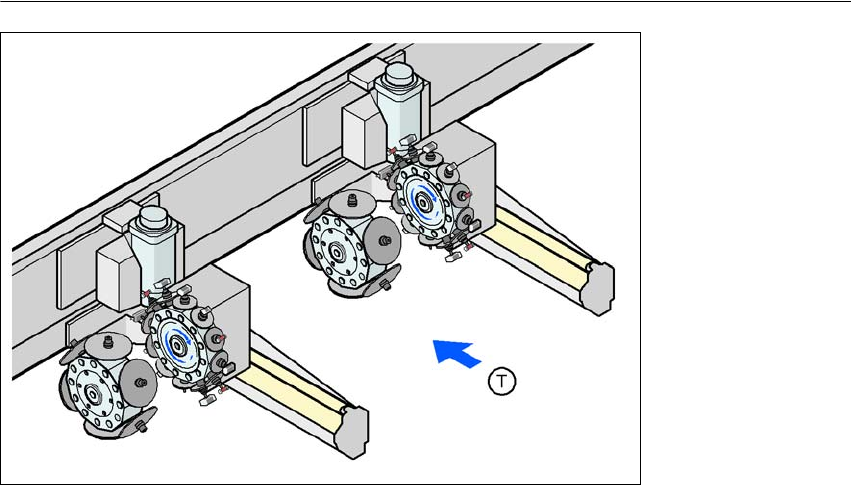
Example:
Stationary PCB conveyor edge on the right: Gantry 1 set up with a 12-segment
Collect&Place head
Gantry 2 set up with a 6-segment Collect&Place
head
1
Fig. 1.1 - 2 Head modularity - SIPLACE D2
G1 Gantry 1
G1 Gantry 2
T Direction of PCB transport
Using the head modularity principle developed by SIPLACE, the Collect&Place heads can be
changed very quickly indeed.
The SIPLACE D2 placement machine is prepared to place 01005 components as standard. For
placement of 01005 components you simply need the optional 01005 package for the 12-segment
Collect&Place head.
The SIPLACE D2 placement machine processes a component range from 01005 to 27 x 27 mm²
at high speed. The components are optically centered using digital vision modules. Either the
standard camera or the high-resolution camera can be installed on the 12-segment Collect&Place
head.
Two component trolleys can be docked into SIPLACE D2 machines for providing components.
A three-part PCB conveyor, consisting of input belt, processing belt and output belt, carries the
PCB into the processing position. As a further variant, it is also possible to choose between the
single conveyor or flexible dual conveyor with fixed side on right or left. The flexible dual conveyor
can also be easily reconfigured to form a single conveyor.
C&P12
G1
C&P6
C&P12
C&P6
G2
User Manual SIPLACE D1/D2 1 Introduction
From software version SR.605.xx 07/2008 EN Edition 1.1 Description of the machine
19
The PCBs are optically centered with the digital PCB camera.
1.1.3 Selecting the placement head configuration
When you order a SIPLACE D-series placement system, you can select the ideal head configu-
ration for your needs. The placement system will be configured and supplied as per your order.
There is also a reconfiguration kit if you wish to change the placement head locally. This package
contains the necessary assembly parts, cables, etc., in addition to the placement head. Before
changing the placement head, you should first adapt the station and SIPLACE Pro software. The
system will then have to be recalibrated.
Head modularity, i.e. adapting the machine to the production requirements by changing the place-
ment head, has the advantage that it is an easy way to match the machine to your production
needs without having to invest in further machines.
1
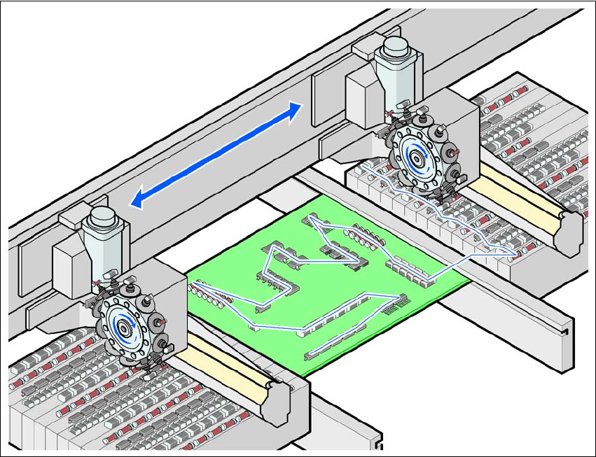
1.1.4 The SIPLACE principle
The placement heads fetch the components from the fixed feeder modules on the component trol-
ley or from the waffle-pack changer, and place the PCBs, which are also stationary. on the dual
conveyor, two PCBs can be placed concurrently.
The principle of the "stationary component supply" and "stationary PCB", which has proved most
suitable for all SIPLACE machines, has a number of significant advantages:
– There are no downtimes for topping up components or splicing tapes.
– The vibration-free component feeder means that even the smallest components (e.g. 01005)
are picked up reliably.
– The PCB, which does not move during the placement process, prevents the components slip-
ping.
– The combination of placement heads with nozzle changers always guarantees an optimum
nozzle configuration for every placement process, thus minimizing traversing paths and opti-
mizing the placement sequence.
High flexibility, cost-effectiveness and set-up reliability combine to ensure that the SIPLACE D1/
D2 provides high productivity. Minimum down times increase utilization and thus help to increase
productivity.
1 Introduction User Manual SIPLACE D1/D2
1.1 Description of the machine From software version SR.605.xx 07/2008 EN Edition
20
1
Fig. 1.1 - 3 The SIPLACE principle
1.1.5 New options and performance features
The following options are available to extend the machines' functionality:
– 01005 package
The SIPLACE D1 and D2 placement machines are prepared to place 01005 components as
standard. For placement simply retrofitting of the 12 segment Collect&Place head with the
01005 package is necessary. 1
– 01005 tape feeder module
The tape feeder module specially developed for 01005 components makes components
available of the sizes 01005 to 0402. 1
– 3x8mm SL tape feeder module
SL means shutterless, that is without a component cover. Dispensing with unnecessary me-
chanical parts reduces the procurement and maintenance costs for this feeder module. 1