00195741-0102_UM_D1_D2_SR605_EN.pdf - 第83页
User Manual SIPLACE D1/D2 2 Operational safety From software version SR.605.xx 07/2008 EN Edition 2.7 Residual voltages and dischar ge times in the machine 83 2.7.1 Operating volt ages, r esidual voltages and disch arge …
2 Operational safety User Manual SIPLACE D1/D2
2.7 Residual voltages and discharge times in the machine From software version SR.605.xx 07/2008 EN Edition
82
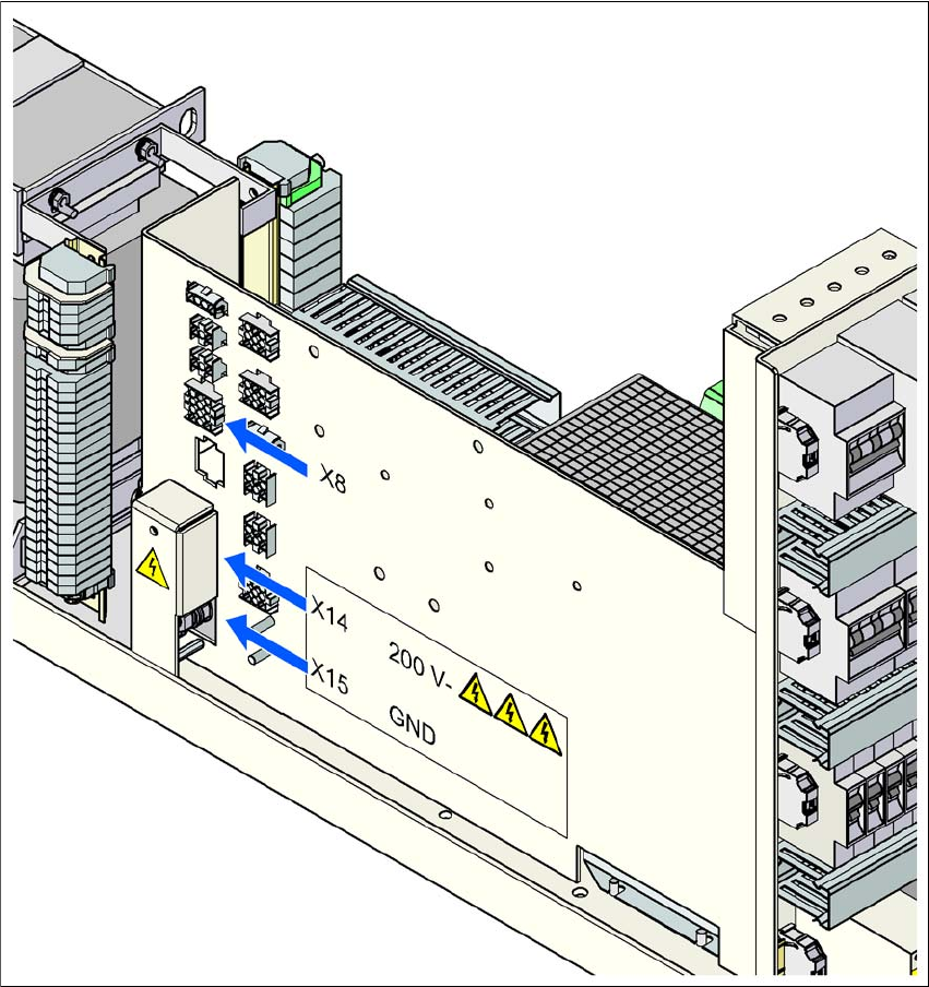
Fig. 2.7 - 2 Measuring points on the power supply unit
2
User Manual SIPLACE D1/D2 2 Operational safety
From software version SR.605.xx 07/2008 EN Edition 2.7 Residual voltages and discharge times in the machine
83
2.7.1 Operating voltages, residual voltages and discharge times after pressing
the emergency stop button
2
2
2
2
2
2.7.2 Residual voltages and discharge times after switching off at the main switch
2
CAUTION 2
To avoid losing data, assess the following criteria before switching off your machine (apart from in
emergencies):
– Has the machine finished transmitting machine, setup and panel data?
– Has the machine finished processing the PCB?
– Has the machine completed the run-up phase?
Pin X14 and connector X8:1
measured to X15 (GND)
Voltage in
normal mode
Residual voltage
after
EMERGENCY
STOP
Discharge
times
X14 + 198 VDC < 60 VDC 4 s
X8:1 + 132 VDC < 60 VDC 1 s
Pin X14 and connector X8:1
measured to X15 (GND)
Residual voltages when
main power switch is off Discharge times
X14 < 60 VDC 4 s
X8:1 < 60 VDC 1 s
2 Operational safety User Manual SIPLACE D1/D2
2.8 Disabling the compressed air supply and discharging the pressure From software version SR.605.xx 07/2008 EN Edition
84
2.8 Disabling the compressed air supply and discharg-
ing the pressure
The compressed air working pressure of the machine is set to 0.52 ± 0.01 MPa (5.2 ± 0.1 bar).
The position of the compressed air unit is indicated by Fig. 2.8 - 1
, page 85. The compressed air
supply to the machine can be interrupted using the shutoff valve (item 1 in Fig. 2.8 - 1
, page 85).
→ Use the machine key to release the cover lock.
→ Lift off the cover (see Fig. 2.8 - 1
, page 85).
→ Turn the lever on the shutoff valve (item 1 in Fig. 2.8 - 1
, page 85) from the vertical to the
horizontal position.
→ Watch the working pressure gauge (item 4 in Fig. 2.8 - 1
, page 85). When the machine is
switched on, the pressure discharges to 0 MPa (0 bar) within 1 minute.
CAUTION
When the machine is switched on, do not use the stop valve to interrupt the compressed air sup-
ply for more than 30 minutes. If you need to shut off the pneumatic system for longer in order to
carry out preventive maintenance or servicing work, you must switch the machine off at the main
switch and disconnect it from the power supply.