00195741-0102_UM_D1_D2_SR605_EN.pdf - 第310页
6 Station extensions User Manual SIPLACE D1/D2 6.16 Coplanarity laser module From software version SR.605.xx 07/2008 EN Edition 310 6.16.5 Position of the coplanarity laser module on th e D1 machine 6 Fig. 6.16 - 4 Posit…

User Manual SIPLACE D1/D2 6 Station extensions
From software version SR.605.xx 07/2008 EN Edition 6.16 Coplanarity laser module
309
6.16.3 Technical data
6
6
6
6.16.4 Restrictions
– The component must have a minimum of two and a maximum of four rows of gullwing leads.
– The row of leads should be located orthogonally to each other.
– The leads should be trained orthogonally to the row of leads.
– The ends of the leads lie on a straight line.
– Measurement of components with just one row of leads is not possible.
Components Gullwing
Accuracy ± 18.5 µm (3σ) (reference component)
± 24.7 µm (4σ)
± 30.5 µm (3σ) (components up to 32 mm)
± 40.7 µm (4σ)
± 31.3 µm (3σ) (components up to 55 mm)
± 41.7 µm (4σ)
Max. component size 55 x 55 mm²
Min. lead pitch 300 µm
Max. component height 25 mm
Positioning option Location 2
Placement head type TwinHead
6 Station extensions User Manual SIPLACE D1/D2
6.16 Coplanarity laser module From software version SR.605.xx 07/2008 EN Edition
310
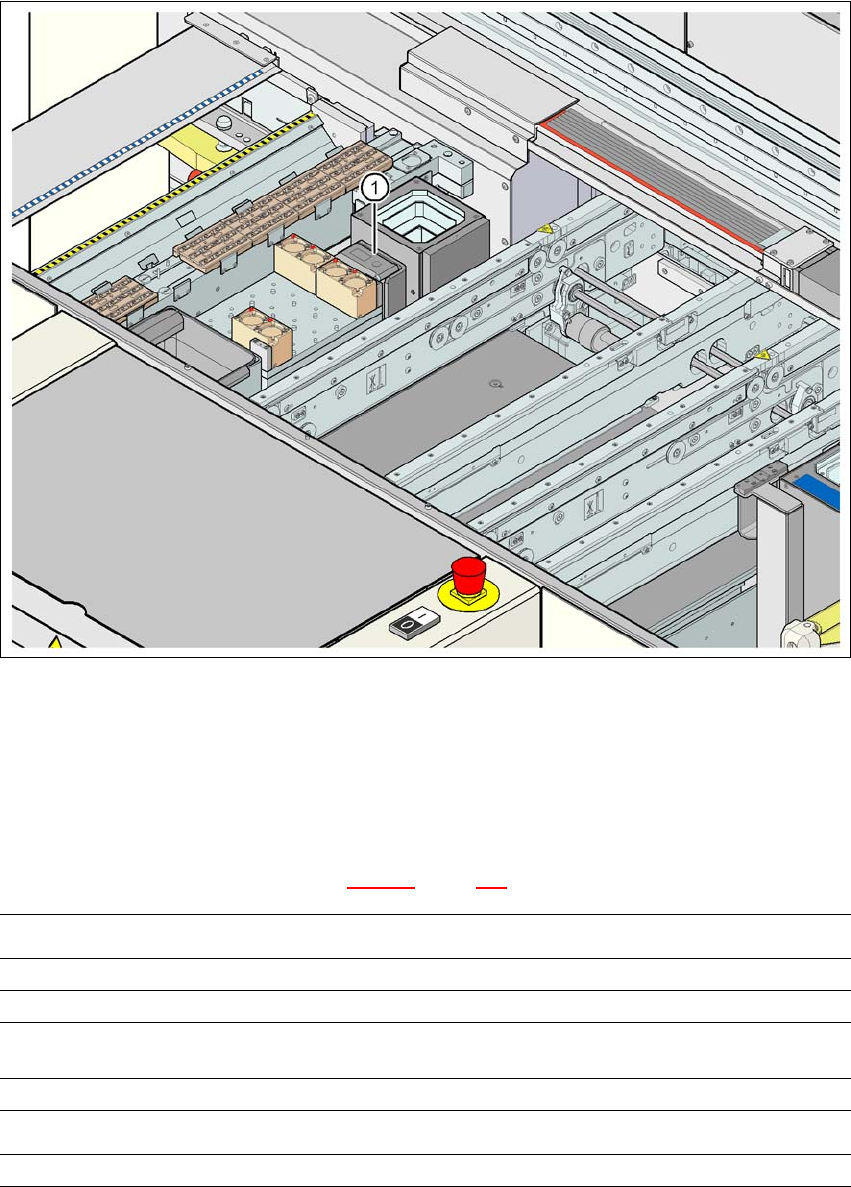
6.16.5 Position of the coplanarity laser module on the D1 machine
6
Fig. 6.16 - 4 Position of the coplanarity laser module on the D1 machine
(1) Coplanarity laser module
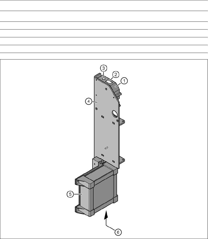
6.16.6 LED displays on the controller
The statuses of the coplanarity module are indicated by LEDs. The LEDs can be found at the bot-
tom of the controller (see item 6 in Fig. 6.16 - 5
, page 311).
LED state Status display
Green Test object in measuring range
Yellow Middle of measuring range
Red
Outside the measuring range,
with low reflection
LED Off Laser switched off
LED Power Status display
LED lights up Supply voltage present
User Manual SIPLACE D1/D2 6 Station extensions
From software version SR.605.xx 07/2008 EN Edition 6.16 Coplanarity laser module
311
6
Fig. 6.16 - 5 Coplanarity laser module
(1) Laser sensor
(2) Detector
(3) Laser emitter
(4) Assembly bracket
(5) Controller
(6) LED displays and connections on the controller
LED avg avg1 avg2
Off Off No averaging
Red Off Averaging 1
Off Red Averaging 2
Red Red Averaging 3
LED state Status display