00195741-0102_UM_D1_D2_SR605_EN.pdf - 第300页
6 Station extensions User Manual SIPLACE D1/D2 6.10 Feeder module cover flap From software version SR.605.xx 07/2008 EN Edition 300 6.10 Feeder module cover flap Item no. 001 19810-xx Feeder module cove r flap, locations…
User Manual SIPLACE D1/D2 6 Station extensions
From software version SR.605.xx 07/2008 EN Edition 6.9 Magnetic pin support
299
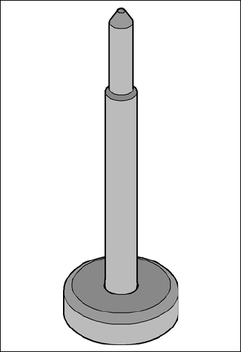
6.9 Magnetic pin support
Item no. 00119680-xx Magnetic pin support
Wide boards tend to deflect during placement such that, under certain circumstances, the compo-
nents can no longer be placed with the desired accuracy. Highly curved PCBs also affect the
placement accuracy. This problem can be easily rectified by fitting magnetic pin supports on the
lifting table.
6
Fig. 6.9 - 1 Magnetic pin support
6 Station extensions User Manual SIPLACE D1/D2
6.10 Feeder module cover flap From software version SR.605.xx 07/2008 EN Edition
300
6.10 Feeder module cover flap
Item no. 00119810-xx Feeder module cover flap, locations 1 and 2, D1
Item no. 00119811-xx Feeder module cover flap, location 2, D1
Item no. 00119812-xx Feeder module cover flap, location 1, D1
Item no. 00119854-xx Feeder module cover flap, location 1, D2
Item no. 00119855-xx Feeder module cover flap, locations 1 and 2, D2
Item no. 00119856-xx Feeder module cover flap, location 2, D2
6
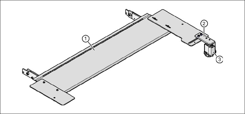
The feeder module cover flap is installed over the component feeder area. It is designed to prevent
a head crash with an upright feeder module retainer that has not been engaged correctly. The
feeder module cover flap can also prevent the front panel of feeder modules entering the place-
ment head traveling range due to incorrect operation.
In addition, a head crash is prevented when a component trolley is changed if the placement head
is over the feeder modules. The component table cannot be raised by pressing the push-button
until the placement head is outside the feeder modules and the cover flap has been opened.
6
Fig. 6.10 - 1 Feeder module cover flap
(1) Feeder module cover flap
(2) Mechanical lock
(3) Switch in the EMERGENCY STOP circuit
The switch for the feeder module cover flap is looped into the EMERGENCY STOP circuit. The
feeder module cover flap must be locked mechanically, which causes the switch to close the open
EMERGENCY STOP circuit.
User Manual SIPLACE D1/D2 6 Station extensions
From software version SR.605.xx 07/2008 EN Edition 6.11 Component sensor for the C&P12 head
301
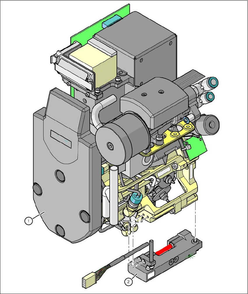
6.11 Component sensor for the C&P12 head
Item no. 00118021-xx Component sensor for the 12-segment C&P head
6
Fig. 6.11 - 1 12-segment Collect&Place head with component sensor
(1) 12-segment Collect&Place head
(2) Component sensor