00195741-0102_UM_D1_D2_SR605_EN.pdf - 第170页
3 Technical data for the machine User Manual SIPLACE D1/D2 3.11 Component trolley From software version SR.605.xx 07/2008 EN Edition 170 3.1 1 Component trolley Item no. 00119822 -xx Component trolley SIPLACE D1/D2 One o…
User Manual SIPLACE D1/D2 3 Technical data for the machine
From software version SR.605.xx 07/2008 EN Edition 3.10 Feeder modules
169
The Dip module is suitable for all the placement heads. It is regarded as a separate feeder module
type by the set-up optimization. There is no limit to the number of dip modules at the individual
locations.
3.10.10.2 Technical data
Locations filled 3 3
Component size Max. 36 x 36 mm²
depending on the placement head type 3
Possible coating thicknesses 25, 35, 45, 55, 65, 75 μm 3
Time required to change the coating thickness Less than 1 min. 3
Gap height tolerance ± 5 μm 3
Time for 1 revolution of the table Can be set using the potentiometer
from 0 - 10 s 3
Component dip time Programmable from 0 - 2 s
in 0.1 s increments 3
Flux Highly viscous flux, conductive adhesive 3
Further technical data and information on programming can be found in the Betriebsanleitung
DIP-Modul / DIP Module User Manual, item no. 00195065-xx.
3
3 Technical data for the machine User Manual SIPLACE D1/D2
3.11 Component trolley From software version SR.605.xx 07/2008 EN Edition
170
3.11 Component trolley
Item no. 00119822-xx Component trolley SIPLACE D1/D2
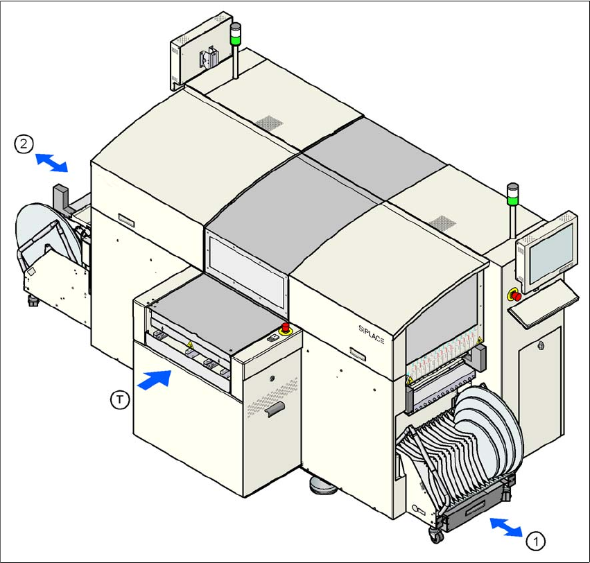
One or two component trolleys can be docked into the machines. The locations are numbered as
shown in the diagram below.
3
Fig. 3.11 - 1 Locations for the component trolleys
(1) Location 1
(2) Location 3
(T) PCB direction of travel
The component trolleys are stand-alone modules that can be set up with feeders at an external
set-up area. This means that the production process only has to be interrupted briefly in order to
change the component trolley.
User Manual SIPLACE D1/D2 3 Technical data for the machine
From software version SR.605.xx 07/2008 EN Edition 3.11 Component trolley
171
PLEASE NOTE: 3
At external set-up positions, you will need an external power supply for the component trolley
(see Section 3.11.5, page 175).
3
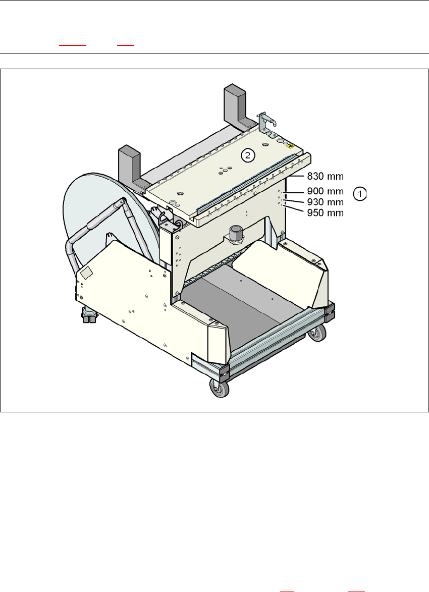
Fig. 3.11 - 2 Component trolley with a PCB conveyor height of 830 mm
3
(1) Holes for the conveyor heights of 830 to 950 mm
(2) Component table
3
Properties
– The trolleys move easily.
– The component trolley is fixed so precisely to the machine that it is even suitable for process-
ing 01005 components.
– The component trolley can be adjusted to PCB conveyor heights of 830 mm, 900 mm, 930
mm and 950 mm in just a few simple actions (see Section 4.4
, from page 216).
– The tape container can hold tape reels with a diameter of up to 15" (optional up to 19").