00195741-0102_UM_D1_D2_SR605_EN.pdf - 第243页
User Manual SIPLACE D1/D2 5 Tasks for the operating personnel From software version SR.605.xx 07/2008 EN Edition 5.4 Changing shift 243 5.4 Changing shif t PLEASE NOTE: 5 Y ou will find additional in formation in the fol…

5 Tasks for the operating personnel User Manual SIPLACE D1/D2
5.3 Note operating status indicator lamp From software version SR.605.xx 07/2008 EN Edition
242
unchanged flashes (7,7) unchanged Transport being initialized
unchanged flashes (7,7) unchanged Place PCB in input conveyor
flashes (1,10) flashes (7,7) unchanged Remove PCB from output conveyor
unchanged flashes (7,7) flashes (1,10) Remove PCB from output conveyor 2
flashes (1,10) flashes (7,7) flashes (1,10) Width adjustment
unchanged flashes (1,10) unchanged Transport PCB
flashes (1,10) flashes (7,7) flashes (1,10) Both output conveyors are cleared
on flashes (1,10) on Conveyor error
on off on Go to service position
on Placement
flashes (1,20) Waiting for processing data
Error display
on off unchanged Machine error, right
on off unchanged Track empty, right
on off unchanged Nozzle configuration, right
on off unchanged Conveyor error, right
on off on Fiducial error, left and right
on off on Fiducial error, left and right
unchanged off on Track empty, left
unchanged off on Nozzle configuration, left
unchanged off on Conveyor error, left
unchanged off on Machine error, left
Pick-up error display
unchanged unchanged flashes (1,20) First track empty, left
unchanged unchanged flashes (5,20) Further tracks empty, left
unchanged unchanged flashes (5,5) Penultimate track in use
unchanged unchanged flashes (1,2) Last track in use, right
flashes (1,20) unchanged unchanged First track empty, right
flashes (5,20) unchanged unchanged Further tracks empty, right
flashes (5,5) unchanged unchanged Penultimate track in use, right
flashes (1,2) unchanged unchanged Last track in use, right
L1 (white)
(right lamp)
L2 (green) L3 (white)
(left lamp)
Meaning

User Manual SIPLACE D1/D2 5 Tasks for the operating personnel
From software version SR.605.xx 07/2008 EN Edition 5.4 Changing shift
243
5.4 Changing shift
PLEASE NOTE: 5
You will find additional information in the following manuals or data media:
– Getting Started with Station Software 605.xx
– SIPLACE D1/D2 preventive maintenance manual
– Parts catalog on the product CD
5.4.1 Activities at shift change
→ Splice the tapes early. The feeder modules do not have to be refilled as soon as the new shift
starts. This minimizes extended down times.
→ At the shift change, pass important information on to the next operator. This includes, for in-
stance, changes to the placement program. Also read through the list of the descriptions of
the steps to take in Section 5.7
, page 251.
→ Carry out a set-up check.
Make sure that the feeder modules are equipped with the correct components, that they are
at the correct locations in the component trolley and that the conveyor increment is set cor-
rectly.
→ Hand over the line in the same state that you would want to find it in when starting your shift.
This means that:
– The rejection containers are empty.
– The waste tape containers are empty.
– The feeder areas have been carefully cleaned with a vacuum cleaner.
5 Tasks for the operating personnel User Manual SIPLACE D1/D2
5.5 Carrying out a walk-through inspection From software version SR.605.xx 07/2008 EN Edition
244
5.5 Carrying out a walk-through inspection
5.5.1 Checking the S feeder modules
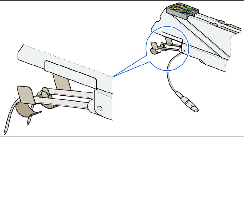
→ Make sure that the tape is correctly placed in the springs of the S feeder module.
5
Fig. 5.5 - 1 Placing the tape in the springs of the S feeder module
→ Check to see whether the tape foil removal container for the S feeder module is full.
If it is full, then pull out the foil and cut it off with scissors.
PLEASE NOTE
Tearing the foil instead of cutting it can lead to problems with the tape removal mechanism.
For this reason the 3 x 8 mm feeder modules are fitted with an integral cutter. This is in the
tape foil removal container at the end of the feeder module under the flaps. 5
→ Check to ensure that the pick-up window on combination feeder modules (24/32 mm) is the
right size for the component.
→ Check to see whether tape guides are inserted on combination feeder modules (24 mm /
32 mm).