00195741-0102_UM_D1_D2_SR605_EN.pdf - 第215页
User Manual SIPLACE D1/D2 4 Setting up and commissioning From software version SR.605.xx 07/2008 EN Edition 4.3 Setting up the machine 215 → Measure th e dista nce between the top e dge of th e PCB conveyor belt and the …
4 Setting up and commissioning User Manual SIPLACE D1/D2
4.3 Setting up the machine From software version SR.605.xx 07/2008 EN Edition
214
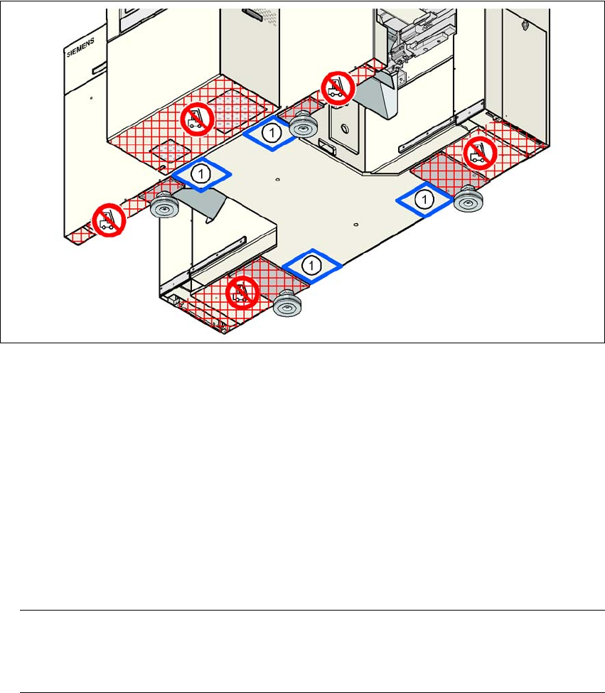
4.3.8.4 Aligning the machine with the air cushion transport system
→ Place the four air cushions of the air cushion transport system beneath the machine frame.
→ Raise the machine and align it with respect to the line.
→ Check the distance from the PCB conveyor system of the adjacent machine. It should be be-
tween 1 mm and 3 mm.
→ Lower the machine.
4
Fig. 4.3 - 7 Contact positions for the air cushion transport system
(1) Contact surfaces for the air cushion transport system
4.3.9 Making final adjustments to the machine
→ Place the machine's spirit level on the panels of the PCB conveyor in placement area 1 in
both the X and the Y directions. The PCB conveyor width is preset:
Single conveyor 210 mm
Dual conveyor, track 1 100 mm
Dual conveyor, track 2 210 mm 4
PLEASE NOTE: 4
On the dual conveyor, place the spirit level only on the outer panels of the machine for ad-
justing in the X direction.
User Manual SIPLACE D1/D2 4 Setting up and commissioning
From software version SR.605.xx 07/2008 EN Edition 4.3 Setting up the machine
215
→ Measure the distance between the top edge of the PCB conveyor belt and the floor. This dis-
tance should be 800 mm, 900 mm, 930 mm or 950 mm.
→ Use the size 65 single-head wrench to adjust the machine feet (item 1 in Fig. 4.3 - 2
, page
206
) so that the label on the machine spirit level does not deviate from the zero point for the
required PCB conveyor height.
→ Check the required PCB conveyor height.
→ Once the machine is aligned, tighten the lock nuts on the machine feet.
→ Use the spirit level to ensure that the machine is precisely aligned.
4.3.10 Removing the shipping braces
Remove all the shipping braces from the gantry axes.
4.3.11 Removing the corrosion protection from the guide rails
The machines were given a corrosion protection treatment before they were delivered.
CAUTION 4
– You should therefore remove the corrosion protection from all the axes and bearings when
you traverse the machine axes for the first time during commissioning.
– Grease all the axes and bearings with the grease described in the maintenance instructions.
If the corrosion protection agent is mixed with the bearing grease on the axes this can greatly re-
duce the service life of the bearings and guide rails.
CAUTION 4
Do not allow any alcohol to enter the guide carriages when you clean the guide rails and scale
rods. Alcohol will damage the bearing grease in the guide carriages.
4
4
4 Setting up and commissioning User Manual SIPLACE D1/D2
4.4 Adapting the component trolley to the PCB conveyor height From software version SR.605.xx 07/2008 EN Edition
216
4.4 Adapting the component trolley to the PCB conveyor
height
The component trolley for the S feeder modules can be set to the following PCB conveyor heights
with just a few simple actions:
830 mm ± 15 mm Standard height
900 mm ± 15 mm Option
930 mm ± 15 mm Option
950 mm ± 15 mm SMEMA option 4
4.4.1 Warning instructions
WARNING 4
Only SIPLACE engineers or qualified personnel are permitted to adjust the component trolley
height.
→ Always follow the applicable accident prevention regulations.
→ Remove all the feeder modules from the component table bed if you want to adjust the height
of the component table.
4.4.2 Tools and equipment
You will need the following tools and equipment to adjust the height of the component trolley:
– Allen key, size 5
– Eye-bolt with M12 thread for lifting the component trolley table,
DIN 580 M12-St, item no. 00048350-xx
– Lifting device for raising the component trolley table, carrying capacity at least 80 kg
4.4.3 Changing the component trolley height
WARNING 4
Remove all the feeder modules from the component trolley table bed.