00195741-0102_UM_D1_D2_SR605_EN.pdf - 第141页
User Manual SIPLACE D1/D2 3 Technical data for the machine From software version SR.605.xx 07/2008 EN Edition 3.9 Vision system 141 3.9.4 PCB camera, type 34, digital 3.9.4.1 Structure 3 Fig. 3.9 - 5 PCB camera, type 34,…
3 Technical data for the machine User Manual SIPLACE D1/D2
3.9 Vision system From software version SR.605.xx 07/2008 EN Edition
140
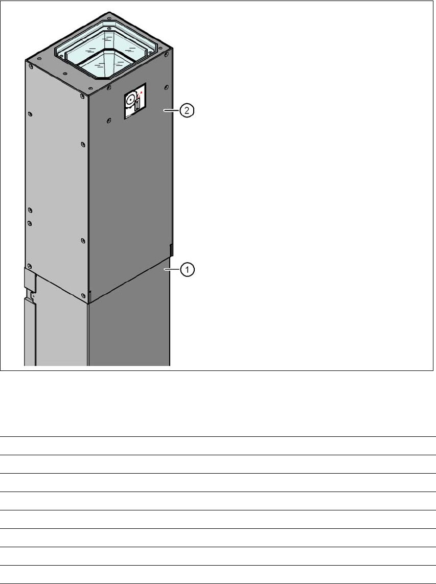
3.9.3 Stationary P&P component camera, type 36, 32 x 32, digital
3.9.3.1 Structure
3
Fig. 3.9 - 4 Structure for the stationary P&P component camera, type 36, 32 x 32, digital
3.9.3.2 Technical data
3
(1) Camera housing with integral camera
and camera amplifier
(2) Glass plate - over the illumination and
lens levels
Component dimensions 0.8 x 0.8 mm² to 32 x 32 mm² (single measurement)
Range of components 0603, MELF, SO, PLCC, QFP, electrolytic capacitors, BGA
Min. lead pitch 0.4 mm
Min. lead width 0.24 mm
Min. ball pitch 0.56 mm
Min. ball diameter 0.32 mm
Field of vision 38 x 38 mm²
Method of illumination Front-illumination (6 levels, programmable as required)
User Manual SIPLACE D1/D2 3 Technical data for the machine
From software version SR.605.xx 07/2008 EN Edition 3.9 Vision system
141
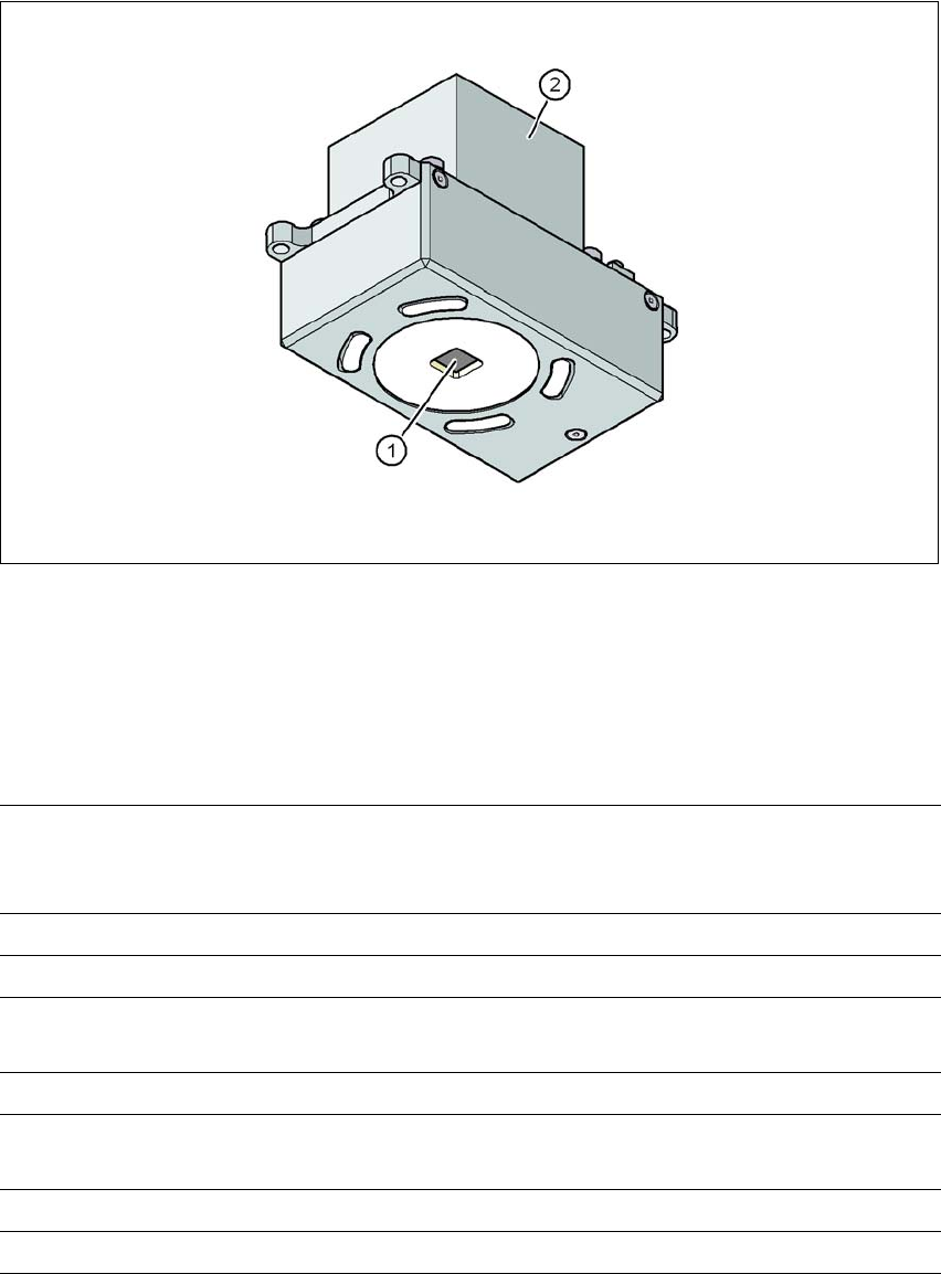
3.9.4 PCB camera, type 34, digital
3.9.4.1 Structure
3
Fig. 3.9 - 5 PCB camera, type 34, digital
(1) PCB camera lens and illumination
(2) Camera amplifier
3.9.4.2 Technical data
3
PCB fiducials Up to 3 (subpanels and multiple panels),
up to 6 for the Long board option (optional PCB fiducials are
output by the optimization).
Local fiducials Up to 2 per PCB (may be of different type)
Library memory Up to 255 fiducial types per subpanel
Image analysis Edge detection method (Singular feature) based on grayscale
values
Method of illumination Front-illumination (3 levels, programmable as required)
Detection time per fiducial
/Bad fiducial
20 ms - 200 ms
Field of vision 5.78 x 5.78 mm²
Distance from the focus plane 28 mm

3 Technical data for the machine User Manual SIPLACE D1/D2
3.9 Vision system From software version SR.605.xx 07/2008 EN Edition
142
3.9.4.3 Fiducial criteria
3
Locate 2 fiducials
Locate 3 fiducials
X-/Y-position, rotation angle, mean PCB distortion
in addition: shear, distortion in X- and Y-direction separately
Fiducial shapes Synthetic fiducials: circle, cross, square, rectangle, rhombus,
circular, square, and rectangular contours, double cross
any pattern
Fiducial surface
Copper
Tin
Without oxidation and solder resist
Warp ≤ 1/10 of structure width, both with good contrast to
environment
Dimensions of synthetic fiducials
Min. X/Y size for circle and rectangle:
Min. X/Y size for annulus and rectangle:
Min. X/Y size for cross:
Min. X/Y size for double-cross:
Min. X/Y size for rhombus:
Min. frame width for annulus and rectangle:
Min. bar width / bar distance for cross, double-cross:
Max. X/Y size for all fiducial shapes:
Max. bar width for cross, double-cross:
Min. tolerances, general:
Max. tolerances, general:
0.25 mm
0.3 mm
0.3 mm
0.5 mm
0.35 mm
0.1 mm
0.1 mm
3 mm
1.5 mm
2% of nominal dimension
20% of nominal dimension
Dimensions of patterns
Min. size
Max. size
0.5 mm
3 mm
Fiducial environment Clearance around reference fiducial not necessary if there is no
similar fiducial structure in the search area.