00195741-0102_UM_D1_D2_SR605_EN.pdf - 第287页
User Manual SIPLACE D1/D2 6 Station extensions From software version SR.605.xx 07/2008 EN Edition 6.3 Component camera for the Pick&Place head 287 6.3.2 St ationary P&P compone nt camera, type 33, 55 x 45, digita…
6 Station extensions User Manual SIPLACE D1/D2
6.3 Component camera for the Pick&Place head From software version SR.605.xx 07/2008 EN Edition
286
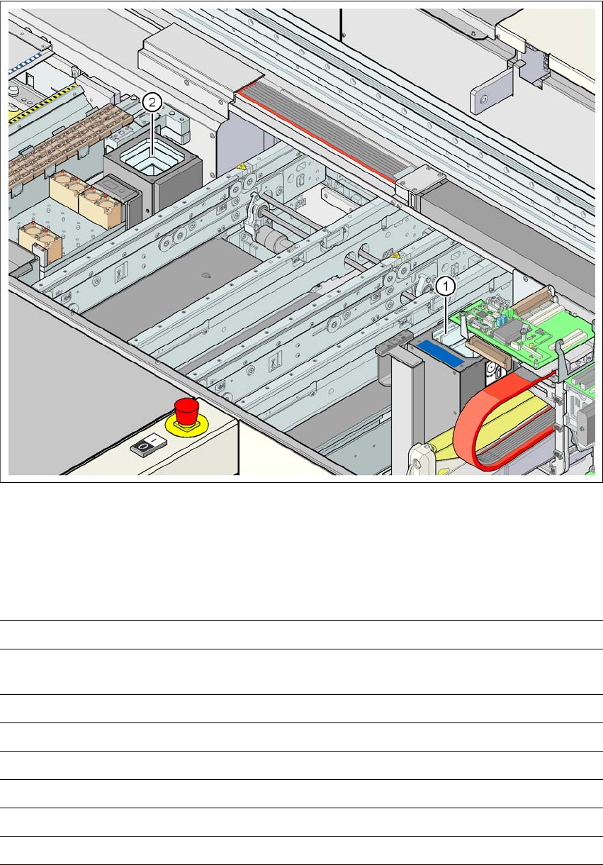
6.3.1.1 Position of the component cameras for the Pick&Place head on the D1 machine
6
Fig. 6.3 - 2 Position of the component camera for the Pick&Place head on the D1 machine
(1) Assembly position for the stationary CO camera, P&P, type 36 (32 x 32) or type 33 (55 x 45)
(2) Assembly position for the stationary CO camera, P&P, type 25 (16 x 16)
6.3.1.2 Technical data, component camera, stationary, P&P, type 25
6
Component dimensions 0.2 x 0.2 mm² up to 16 x 16 mm² for single component measurement
Range of components 0201 to SO, PLCC, QFP, sockets, plugs, BGA, special components,
bare dies, flip-chips, shields
Min. lead pitch 0.25 mm
Min. lead width 0.1 mm
Min. ball pitch 0.14 mm
Min. ball diameter 0.08 mm
Field of vision 19.4 x 19.4 mm²
Method of illumination Front-illumination (6 levels, programmable as required)
User Manual SIPLACE D1/D2 6 Station extensions
From software version SR.605.xx 07/2008 EN Edition 6.3 Component camera for the Pick&Place head
287
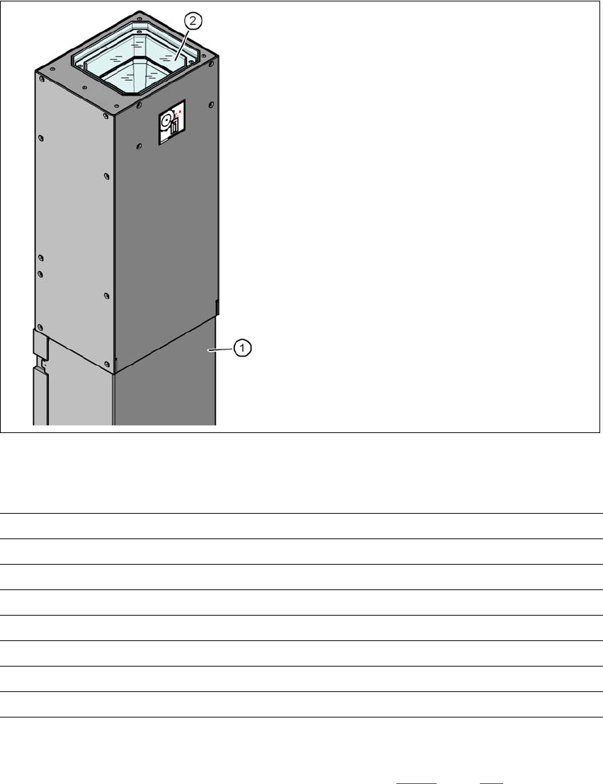
6.3.2 Stationary P&P component camera, type 33, 55 x 45, digital (fine-pitch
camera)
Item no. 00119818-xx Stationary component camera, type 33, digital (55 x 45)
6
Fig. 6.3 - 3 Stationary P&P component camera, type 33, 55 x 45, digital (fine-pitch camera)
6.3.2.1 Technical data
6
6.3.2.2 Position
The position of the fine-pitch camera, type 33, is shown in Fig. 6.3 - 2, page 286.
(1) Camera housing with integral camera
and camera amplifier
(2) Glass plate - over the illumination and
lens levels
Component dimensions 0.5 x 0.5 mm² to 55 x 45 mm²
Range of components 0402, MELF, SO, PLCC, QFP, electrolytic capacitors, BGA
Min. lead pitch 0.3 mm
Min. lead width 0.15 mm
Min. ball pitch 0.35 mm
Min. ball diameter 0.2 mm
Field of vision 65 x 50 mm²
Method of illumination Front-illumination (6 levels, programmable as required)

6 Station extensions User Manual SIPLACE D1/D2
6.4 PCB barcode scanner From software version SR.605.xx 07/2008 EN Edition
288
6.4 PCB barcode scanner
6.4.1 Description
Item no. 00119682-xx 1D PCB barcode scanner
Item no. 00119679-xx 2D PCB barcode scanner
Item no. 00119430-xx PCB barcode scanner assembly kit
The PCB barcode scanner is used to automatically record and decode barcodes on PCBs. The
PCB barcode scanner sends the read data via its serial interface to the transport controller and
then for further processing to the machine controller via the CAN bus.
6
Fig. 6.4 - 1 PCB barcode block diagram
The PCB barcode scanners are installed on the input side of the placement machine on the PCB
conveyor. Up to four devices can be retrofitted to each machine. The barcode scanners are fitted
so that the barcode labels on the topside and underside of the PCBs can be scanned on both
tracks of the dual conveyor.
There are two variants of the barcode scanner:
– 1D barcode scanner
This barcode scanner processes barcodes. 6
– 2D barcode scanner
This barcode scanner processes matrix code. Matrix code is primarily used when there is
not enough space for barcode labels. The 2D barcode scanner also reads conventional
barcodes. 6
Device number
1
BC
scanner
top
Distribution
board
Transport
controller,
right
BC
scanner
bottom
2
3
BC
scanner
top
Distribution
board
Transport
controller,
left
BC
scanner
bottom
4
Machine
controller
Control
computer
SIPLACE Pro
computer
LANCAN busV-24V-24