00195741-0102_UM_D1_D2_SR605_EN.pdf - 第213页
User Manual SIPLACE D1/D2 4 Setting up and commissioning From software version SR.605.xx 07/2008 EN Edition 4.3 Setting up the machine 213 → Make sure that the for ks are evenly load ed when you lift the machine. A firm …
4 Setting up and commissioning User Manual SIPLACE D1/D2
4.3 Setting up the machine From software version SR.605.xx 07/2008 EN Edition
212
4.3.8 Integrating the machine into the line
→ Note the warning instructions described in Section 4.3.2, page 203.
→ The tools and equipment are listed in Section 4.3.3
, page 204.
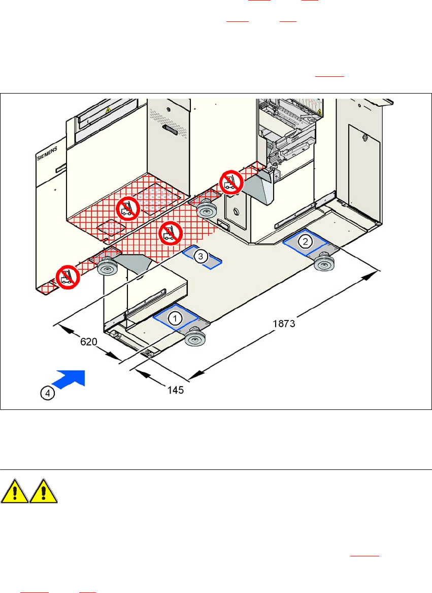
4.3.8.1 Positioning the fork lift
→ Push the forks of the fork-lift under the machine, as shown in Fig. 4.3 - 6.
4
Fig. 4.3 - 6 Machine attachment surfaces for the fork-lift - dimensions in millimeters
WARNING 4
Please note the following points before you raise the machine in order to avoid irreversible dam-
age to the machine:
→ Attach the fork-lift on the power supply side of the machine (item 4 in Fig. 4.3 - 6
).
→ Make sure that the machine attachment surfaces 1, 2 and 3 lie evenly on the fork (see Fig.
4.3 - 6
, page 212). Use wooden planks of appropriate length for support, if the fork is shorter.

User Manual SIPLACE D1/D2 4 Setting up and commissioning
From software version SR.605.xx 07/2008 EN Edition 4.3 Setting up the machine
213
→ Make sure that the forks are evenly loaded when you lift the machine. A firm support between
the forks and machine will prevent the machine tilting when it is raised. This will also prevent
a one-sided load on the machine feet, which would deform the fixing of the machine feet. We
recommend that a second person watch the machine as it is raised, and make sure that the
machine does not tip to one side when lifted with the fork-lift.
4
4
4
4.3.8.2 Points that MUST be noted when transporting the machine
WARNING 4
When you are transporting the machine, make sure that all the feet are clear of the floor. If they
are not clear, the feet will drag along the floor or bump into obstacles. This could damage the
machine foot fixing in the machine frame.
4.3.8.3 Aligning the machine with respect to the line
→ Position the machine on the free location on the line using the fork-lift.
WARNING 4
Lower the machine slowly. A second person should look underneath to ensure that all the
machine foot touch the floor at the same time. If the machine feet on one side hit the ground
hard, the fixings may be damaged.
4
4 Setting up and commissioning User Manual SIPLACE D1/D2
4.3 Setting up the machine From software version SR.605.xx 07/2008 EN Edition
214
4.3.8.4 Aligning the machine with the air cushion transport system
→ Place the four air cushions of the air cushion transport system beneath the machine frame.
→ Raise the machine and align it with respect to the line.
→ Check the distance from the PCB conveyor system of the adjacent machine. It should be be-
tween 1 mm and 3 mm.
→ Lower the machine.
4
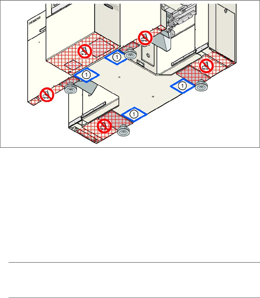
Fig. 4.3 - 7 Contact positions for the air cushion transport system
(1) Contact surfaces for the air cushion transport system
4.3.9 Making final adjustments to the machine
→ Place the machine's spirit level on the panels of the PCB conveyor in placement area 1 in
both the X and the Y directions. The PCB conveyor width is preset:
Single conveyor 210 mm
Dual conveyor, track 1 100 mm
Dual conveyor, track 2 210 mm 4
PLEASE NOTE: 4
On the dual conveyor, place the spirit level only on the outer panels of the machine for ad-
justing in the X direction.